
User's Manual
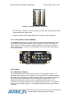
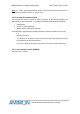
Table Of Contents
- 1. Purpose
- 2. The System
- 3. Setting-up a Link
- 4. System Configuration
- 5. User Interface
- 5.1 Video Input selection
- 5.2 Video input status Tx & Rx
- 5.3 Registration (both Tx and Rx)
- 5.4 Association (Tx & Rx)
- 5.5 RF frequencies table selection
- 5.6 Manual Transmission power (Tx only)
- 5.7 Manual frequency selection
- 5.8 Broadcast mode (both Tx and Rx)
- 5.9 Link exists (both Tx and Rx)
- 5.10 Communication error (both Tx and Rx)
- 5.11 DVI mode (Rx Only)
- 6. Basic Troubleshooting

WHDI Reference Design Setup Guide
Dev Kit-UG1_Rev 1.0.28
Figure 1 – wireless modules connectors
- The board also contains a remote control IR receiver port (optional) that will be
supported with later SW versions.
- The power supply of the Seagull board is 5V 2A center positive DC power.
2.1.3 User Interface board (AMN060)
The AMN060 User Interface (UI) board is used to perform several operations, such
as registration, display link status etc. Figure 2 shows the picture of the Interface
board, that later on in this document will be illustrated as a schematic drawing for
clarity. Please refer to chapter 5 for a description of the various LEDs and buttons
use and indications.
Figure 2 - User Interface Board
2.2 Rx side
2.2.1 Wireless Rx Board
The Shaldag Wireless Rx board is the reception part of AMIMON's system. The
board has 5 printed antennas, 4 of which are for reception and 1 alternates between
reception and transmission of the back-channel (uplink). The board also contains the
RF components, the Baseband Rx chip and the MAC microprocessor. On the
Shaldag board the MAC microprocessor is embedded inside the BB chip. It is
connected to the Seagull interface board through a WHDI connector. The wireless
board gets its 5V power supply from the Seagull interface board through the WHDI
connector.
Confidential Under NDA
Internal document. Information subject to change
9 Page