AMN41012 and AMN42012 Installation Manual An AMIMON Ltd.. Document Copyright 2018 Version 1.0 Amimon Ltd. 26 Zarhin St. Raanana, Israel. Tel: +972-9-9629222 www.amimon.com 2017 © All rights reserved to Amimon ltd.
Table of Contents Table of Contents S Y Z 0 1 0 ....................................................................... 2 M Important Notice......................................................................... 3 Revision History .......................................................................... 4 Safety Instructions ..................................................................... 5 Introduction ................................................................................
Important Notice AMIMON Ltd. reserves the right to make corrections, modifications, enhancements, improvements, and other changes to its products and services at any time and to discontinue any product or service without notice. Customers should obtain the latest relevant information before placing orders and should verify that such information is current and complete. All products are sold subject to AMIMON's terms and conditions of sale supplied at the time of order acknowledgment.
Revision History Version Date Description 1.0 Jan 2,2019 Initial Release Amimon Ltd. 26 Zarhin St. Raanana, Israel. Tel: +972-9-9629222 www.amimon.com 2017 © All rights reserved to Amimon ltd.
Safety Instructions When operating this equipment, read and follow all the instructions in this manual Do not open unit Do not block air ventilation Use only accessories/batteries/ power supplies provided, specified or recommended by AMIMON. When devices are switched on keep away at least 20 cm from your body. People with pacemakers should ALWAYS keep the device at the listed distance from their pacemaker when turned ON.
Introduction The AMN41012 and AMN42012 are wireless video system comprising of a video transmitter and video receiver modules, that operate at the 5GHz unlicensed band. It is are based on AMIMON's Professional chipset that consist of the AMN2130 and AMN2230 baseband receiver and the MAXIM 2850 and 2851 ICs, providing the ultimate solution for 4K Video transmission.
AMN42012 Non-DFS Frequencies : Frequency Control: 5.150~ 5.250 GHz for EU 5.150 ~ 5.250 GHz and 5.725~5.825 GHz for US DFS Frequencies (used only in Aerial mode): 5.250-5.350 GHz and 5.470 ~ 5.725 GHz for EU 5.250-5.330 GHz and 5.470 ~ 5.725 GHz for US 5.250-5.350 GHz and 5.470 ~ 5.6GHz and 5.650 ~ 5.710 GHz for Canada SRD Frequencies (EU): 5.725 ~ 5.
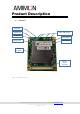
Product Description (1) AMN41012 Video LED Network LED 2dBi or 5dBi Antenna Power LED Reset button Pairing button Boot button Debug Connector Board-toboard connector Figure 1 –AMN41012 top view Amimon Ltd. 26 Zarhin St. Raanana, Israel. Tel: +972-9-9629222 www.amimon.com 2017 © All rights reserved to Amimon ltd.
(2) AMN42012 2dBi or 12dBi Antenna 2dBi Omni Antenna Reset button Video LED Pairing button Boot button Power LED Network LED Debug Connector Board-toboard connector Figure 2 – AMN42012 top view Amimon Ltd. 26 Zarhin St. Raanana, Israel. Tel: +972-9-9629222 www.amimon.com 2017 © All rights reserved to Amimon ltd.
(3) LED behaviors Network LED Flashing Rate Indication Fast blinking (errors) Stuck in bootloader / MAC not alive / No XML / default calibration Off Not registered to TX / power down / disconnected/ Waiting for user response at registration Normal blinking Searching for TX Fast blinking During registration / out of range On In link Table 3 - Network LED Video LED Flashing Rate Indication Fast blinking (errors) Stuck in bootloader / MAC not alive / No XML / default calibration Off Not r
(4) Board-to-Board Connector The Interface connector provides various interfaces to communicate between the module and the MCU to configure video related parameters and settings, or receive the network status and communication related parameters.
Installation The modules are designed to be integrated with any compatible Video Interface Board (VIB), to provide a complete wireless Video Solution. At common application, the VIB shall provide standard video interface that can be connected to standard video monitor. This video interface may be HDMI, HD-SDI or any other standard or custom video interface.
See ‘Product Description’ for port location described in this section. 1. Connect AMIMON modules to the compatible Video Interface Board (VIB). 2. Connect the antennas to the modules. Only use antennas provided by AMIMON 3. Connect the receiver VIB to a video monitor through the supported video interface of the VIB. 4. Connect the transmitter VIB to a video source (for example, camera) through the supported video interface of the VIB. 5. Power ON the VIB according to its operating manual. 6.