M5900 Portable Data Terminal User’s Guide © 2008 American Microsystems LTD. Effective Date: January 2008 AML Website: www.amltd.
M5900 PORTABLE DATA TERMINAL User’s Guide Disclaimer American Microsystems, Ltd. reserves the right to make changes in specifications and other information contained in this document without prior notice, and the reader should in all cases consult American Microsystems, Ltd. to determine whether any such changes have been made. The information in this publication does not represent a commitment on the part of American Microsystems, Ltd. American Microsystems, Ltd.
TABLE OF CONTENTS INTRODUCING THE M5900 1 THE M5900 MENU SYSTEM 20 What to Expect 1 Main Menu 20 2 Run Program 21 General Conventions 2 M5900 Settings 21 Barcode Settings 21 M5900 TERMINAL OVERVIEW 3 Security Settings 40 Using the M5900 Keyboard 3 Resume Password 41 Key Values 4 Program Settings 43 The M5900 Display Screen 5 PC Uplink Settings 44 The M5900 Scanner 5 Power Management 47 The M5900 Scanner LED 8 Set Date & Time 48 Scanner information and Labeling 9 Ad
G E T T I N G S T A R T E D 1 Chapter Introducing the M5900 This chapter describes how to get started using your M5900 portable data terminal and get you up and running fast. T he M5900 portable data terminal is an ultra-versatile, high-performance, designedto-fit-your-budget terminal. The ergonomic design easily fits in even the smallest of hands. It is rugged, lightweight, compact and easy-to-use. The high resolution graphical display is capable of presenting a multitude of fonts and images.
G E T T I N G S T A R T E D • Collect and upload data • Send and receive data • Connect and use the M5900 serial and USB interface Warranty A one-year warranty against material defects and workmanship from the date of shipment is guaranteed by American Microsystems, Ltd. Products are sold on the basis of specifications applicable at the time of manufacture. American Microsystems, Ltd. shall have no obligation to modify or update products once sold.
M5900 Keyboard The M5900 has two keyboard options: - 55-key Alphanumeric Keyboard - 35-key Numeric Keyboard SCAN SCAN F1 F2 F3 F4 F5 $@= ABC DEF 1 2 3 GHI JKL MNO 4 5 6 PQRS TUV WXYZ 7 8 9 (|) . #:%& Alpha Esc Menu 0 Ins ENTER Shift Space - The high contrast, color coded overlay surrounding the keyboard keys indicates alternate functions of each key. Pressing a modifier key (Shift, Alt, Ctl, Lock, Unlock, Func) will enable that modification for the next key press only.
2 Chapter M5900 Terminal Overview This chapter describes the features of the M5900 portable data terminal. T o save time in the future, print a copy of this document. Choose Print from the File menu, and press Enter to receive all the pages of examples and instructions. Using the M5900 55-key Keyboard The M5900 Terminal is equipped with fifty-five keys that are divided into white, grey, blue, red, yellow and black keys.
Thirty-three grey keys represent letters, special functions, Space and Menu keys. The [Alt], [Ctl], [Ins], [? ¦ ] (backspace) and [Esc] keys are also grey keys near the bottom of the keyboard. Key Values Yellow Key SCAN Activates the built in scan engine. The red LED above the power key indicates when the scan engine is active. Blue Keys Func Selects special functions determined by the software system. Hitting Func then a number selects a special function.
Using the 35-key Keypad Scan Key SCAN Power Key Backlight Key Lock Key/Green Modifier Unlock Key/Purple Modifier F1 F2 F3 F4 F5 $@= ABC DEF 1 2 3 GHI JKL MNO 4 5 6 PQRS TUV WXYZ 7 8 9 Cursor Keys (|) .
Using the 35-key Keypad - cont’d. Using the Alpha key on the 35-key Keypad If the M5900 hand-held computer is equipped with the numeric keypad, the unit will allow alphabetic input in a mobile phone style interface. Pressing the Alpha key once, will put the keyboard into Alpha Mode. Within Alpha Mode, a numeric key (0 – 9 or period) can be pressed and released multiple times to allow input of any of the three or four red symbols on the key.
Using the 35-key Keypad - cont’d. Using Lock and Unlock on the 35-key Keypad If the user needs to input a large amount of alphabetic data, they can temporarily enable the Alpha-Lock feature by pressing the Lock/Blue Modifier followed by the [Alpha] key. To disable Alpha-Lock, the user can press the Unlock/Yellow Modifier followed by the [Alpha] key. The [Shift] key can be locked and unlocked in the same manner to create a CAPS lock.
White Keys Numeric 0, 1, 2, 3, 4, 5, 6, 7, 8, 9, . (period) and Backlight Lamp. The M5900 Display Screen The M5900 portable data terminal includes a 160 pixel by 160 pixel grayscale graphical Liquid Crystal Display (LCD). Programs can be written which mix text and graphics together on the display. Warning: This display is NOT a touch screen display and the operator should not use sharp objects on the plastic window protecting the LCD display.
Long Range Laser (LR) The Long Range laser engine uses a moving laser light with a highly sensitive laser detector. The long range laser is used when the barcodes are going to be a great distance from the operator. The long range laser includes a laser point (dot) feature to make it easy for the operator to aim at the barcode before it starts to read. Scan Rate: 35 (± 5) Scans / Second Scan Angle: 23º ± 2º Min.
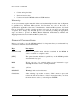
Reading distance for the Standard High Speed Laser Reading distance for the Long Range Laser 7
Reading distance for the Advanced Long Range Laser Barcode symbologies are always measured in mils. This usually refers to the narrowest bar width. One mil equals 0.001”, therefore a 0.01” wide narrow bar would be a 10 mil barcode. Conversion: 1 mil = 0.0254 mm 1 inch = 25.4 mm These charts show typical performance at 68°F on high quality bar code symbols. The M5900 Scanner LED The M5900 has a multi-color LED to indicate when the unit has scanned a bar code successfully.
Scanner information and Labeling The M5900 Integrated Laser Scanner uses a low-power visible laser diode. Avoid staring directly into the light beam. Momentary exposure to a CDRH Class II laser is not known to be harmful. Laser Classification: CDRH Class II Light Source: 630 – 680 nm laser diode Laser Output Power: 1.0 milliwatt maximum output FCC Information: This device complies with Part 15 of the FCC Rules.
10
The Optional M5900 Handle The M5900 has an optional “pistol grip” style handle for users who prefer the point and shoot style. The M5900 handle is secured to the M5900 portable data terminal by 4 screws. The battery is then relocated in the handle for easy change-out.
The M5900 Communications Ports The M5900 has two types of communications ports on the bottom of the unit. 4 3 1 2 10 9 8 7 6 5 4 3 2 1 The two ports are shown here. Description of the RJ-45 10 Pin Connector (RS-232) 1. 5 VDC (out to handheld tethered scanner) 2. RxD (in to terminal) 3. TxD (out from terminal) 4. RTS (out from terminal) 5. GND 6. Battery Charge (in to terminal) 7. CTS (in to terminal) 8. UDC+ (USB data +) 9. UDC – (USB data -) 10.
The M5900 Charger / Serial Adapter The ACC-5910 Terminal Charger charges the M5900 portable data terminal and has a built-in null-modem adapter that allows for RS-232 serial communications. Charging Do not turn the M5900 terminal off and insert the ACC-5910 Modular plug into the bottom of the M5900. It begins to charge as soon as it is inserted. Terminal can not be powered off while on charger.
The Optional M5900 Cradle The M5900 Portable Data Terminal has available, an optional charging and communications cradle. The cradle automatically charges the M5900 battery while it is resting in the cradle. The cradle also includes an extra slot to charge a spare battery. The M5900 cradle can accommodate the M5900 with or without the optional M5900 handle. The M5900 Cradle has three indicator lights: POWER - Indicates that the M5900 Cradle is plugged in.
When the battery charging LED is red, the battery is charging. When the battery charge LED is green the battery is fully charged. A fully discharged battery takes about 6 hours to completely recharge. Warning: The battery will discharge if the charger does not remain plugged in while the M5900 terminal is in cradle or on the charger. The M5900 Cradle’s Communication Ports The M5900 portable data terminal has 2 different styles of communications ports, RS-232 (RJ45) and USB (Type II).
3 Chapter Using the M5900 This chapter describes using the M5900 portable data terminal for the first time. Initial Startup – Cold Boot hen the M5900 is turned on for the first time, it performs a cold boot. The cold boot process loads the operating system into the M5900’s virtual memory so it will execute as fast as possible. This process only takes a few seconds. You should program the current date and time into the real time clock of the M5900 terminal.
Updating the Firmware The M5900 has a built-in function which allows updating of the firmware. The files will be transferred to the M5900 unit over the serial or USB cables. The AML programming utility will be required which is included in the Program Generator package. To upgrade the M5900 firmware you must force a cold boot as described above. When turning the unit back on for the first time press and hold the [Menu], [Space] and [Shift] key simultaneously then press the power key.
The “Receive Files” screen is shown waiting for a response from the PC. At any time the user can hit the [Esc] key to see the Firmware Update Main Menu screen. When finished hit the “Reboot Hand-Held” and wait for the M5900 terminal to decompress and install the files. Once the files are decompressed and stored in memory, the unit will automatically re-boot and start normally. The M5900 firmware is available on the AML website (www.amltd.com).
The M5900 Program Generator In order to write a custom program for the M5900 you must use the M5900 Program Generator. The Program Generator is installed on a Windows® based PC and allows the user to write custom applications with little or no programming skills. These programs along with associated data files are uploaded to the M5900 terminal using the USB or serial connector. Once data is collected information can then be downloaded from the M5900 using the Program generator tools.
4 Chapter The M5900 Menu System This chapter describes the Main Menu functions of the M5900 Portable data Terminal. Main Menu ou may access the menu system by pressing the [Menu] key on the M5900 portable data terminal. The menu screens pop-up in front of the currently displayed screen. Only the items in the menu screens are active when the menu items are displayed. Y The menus can be navigated by using the up and down cursor keys.
Run Program To run an installed program select Run Program then select the appropriate program from the program list. M5900 Settings When you select the Settings menu item you will see the M5900 Settings sub-menu. Barcode Settings The “Barcode Settings” function allows you to make changes to the way specific bar codes are scanned by the internal scan engine.
General Settings STANDARD OPTIONS: Send Type ID ON: Sends a letter preceding the data, indicating the symbology type of the bar code. The letter corresponds to the types: A - Code 39 D - EAN-13 G - Codabar J - MSI/Plessey B - UPC-A E - EAN-8 H - Code 128 K - Code 11 C - UPC-E F - Interleaved 2 of 5 I - Code 93 L - ISBN OFF*: Do not transmit Bar Code Type ID Allow Dup Reads ON*: Enable reading the same bar code multiple times. OFF: Disable reading the same bar code twice in a row.
ADVANCED OPTIONS: Keyboard Input Mode TERM CHAR: ON: Strips any termination character from the bar code that was scanned. OFF*: Does not strip any termination characters from the bar code. The optional Termination Character is transmitted at the end of the data.
Allows the user to override a Termination Character embedded in a bar code. If the bar code has a non-printable termination character, it will be truncated and replaced by the selected termination character. Scanner Settings These options are used to configure the laser or CCD device behavior, and the trigger mode for the M7100 handheld terminal. TRIGGER PULSE Trigger Mode Trigger activates scanning device for as long as trigger is held up to the Laser Timeout value in seconds.
Turns off Laser / CCD after (1 – 9) seconds when the trigger is pushed in Pulse mode, or held down in Trigger mode. The laser / CCD will always turn off immediately after a good read. <--> Read Verify Performs bar code re-reads the number of times (0 – 9) required for applications where accuracy is critical. This is used where the bar code is poorly printed or damaged. Symbologies The “Symbology Settings” function allows you to make changes to each individual bar code.
ON Enable the Mod 43 Check Digit for Code 39. When this option is enabled, only Code 39 labels that contain a valid check digit will be read. OFF* Disable the Mod 43 Check Digit. Check digit verification will not be performed. Send Chk Digit ON Transmit the Mod 43 Check Digit with the bar code data. Requires the “Mod 43 Check Digit” option above to be set on. OFF* Do not transmit the Mod 43 Check Digit. Concatenate Mode ON Enable Concatenate Mode.
OFF Do not transmit the UPC-E Number System character. Send Check Digit ON* Transmit the UPC-E Check Digit character. OFF Do not transmit the UPC-E Check Digit character. UPC-A: Convert to EAN-13 ON Convert all UPC-A labels to an equivalent EAN-13 format by inserting a leading zero. After conversion, the reader will follow the EAN-13 programming options. OFF* No conversions will be performed. Send System ON* Transmit the UPC-A Number System character.
ISBN Conversion ON Convert 13 DIGIT BOOKLAND/EAN (978) prefix to its corresponding 10-digit ISBN number. OFF* Do not convert Bookland/EAN to an ISBN number. EAN-8: Send Country Code ON* Transmit the EAN-8 Country Code. OFF Do not transmit the EAN-8 Country Code. Send Check Digit ON* Transmit the EAN-8 Check Digit character. OFF Do not transmit the EAN-8 Check Digit character. EAN-13 Send Country Code ON* Transmit the EAN-13 Check Digit character.
ON* Enable reading 2 digit supplements. Option 0) above must be set on. OFF Disable reading 2 digit supplements. Allow 5 Digit Sup ON* Enable reading 5 digit supplements. Option 0) above must be set on. OFF Disable reading 5 digit supplements. Require UPC Sup ON* Enable reading UPC supplements. Option 0) above must be set on. OFF Disable reading UPC supplements. Require EAN Sup ON* Enable reading EAN supplements. Option 0) above must be set on. OFF Disable reading EAN supplements.
ON Uniform Symbology Specification (3-1-3 mod 10) OFF* None (no check digit required) OPCC Check Digit Specifies if the OPCC check digit type will be used with Interleaved 2 of 5: ON Optical Product Code Council (2-1-2 mod 10) OFF* None (no check digit required) Send Check Digit ON Transmit the Interleaved 2 of 5 check digit with the bar code data. OFF* The check digit is not transmitted.
CODABAR Send Start / Stop ON Transmit the Codabar start/stop characters. OFF * Do not transmit the Codabar start/stop characters. CLSI Formatting ON The reader will insert a blank after the 1st, 5th, and 10th characters of a 14-character Codabar label. The label length does not include the start and stop characters. OFF * Disable CLSI formatting. CLSI Check Digit ON Enable the CLSI check digit. When this option is enabled, all fourteen digit numeric bar codes must contain a valid check digit.
UCC-128 Verification ON A valid Mod 10 Check Digit is required on UCC-MOD 10 bar codes. (Applies to 20-digit serial shipping container bar codes.) OFF * UCC-MOD 10 bar codes are accepted without valid Mod 10 Check Digits. Send Mod 10 Chk Digi ON * Transmit the Mod 10 Check Digit with the bar code entry. OFF Do not transmit the Mod 10 Check Digit. Send EAN Type ID ON * Transmit the EAN Type ID. OFF Do not transmit the EAN Type ID. CODE 93 Concatenate Mode ON Enable Concatenate Mode.
MSI / PLESSY 2 Chk Digits Required ON Two valid check digits are required for each label. The first check digit is defined by option 2) below. The second check digit is always mod 10. OFF * One valid check digit is required for each label. The check digit must be mod 10. 1st Chk Digit Mod 11 ON The First Check Digit must be mod 11. OFF * The First Check Digit must be mod 10. Send 1st Check Digit ON Transmit the First Check Digit. OFF * Do not transmit the First Check Digit.
CODE 11 2 Chk Digits Required ON Two valid check digits are required for each label. OFF * One valid check digit is required for each label. Send 1st Check Digit ON Transmit the First Check Digit. OFF * Do not transmit the First Check Digit. Send 2nd Check Digit ON Transmit the Second Check Digit. OFF * Do not transmit the Second Check Digit. RSS RSS-14 Active ON* Enable reading the described bar codes.
OFF Disable reading of the described bar codes. RSS Limited Active ON* Enable reading the described bar codes. OFF Disable reading of the described bar codes. RSS Expanded Active ON* Enable reading the described bar codes. OFF Disable reading of the described bar codes. Send EAN Type ID ON Transmit the RSS EAN Type Identifier string. OFF * Do not transmit the RSS EAN Type Identifier string. Application Interface ON* Transmit the 2 digit Application Interface characters.
The “Scan Editing” allows data editing (modification) before transmission. SCAN EDITING Enable Scan Editing Check-box must be checked for any of the editing options below to be valid. Disabled: Disable Data Editing of bar codes. All Types: Enable Data Editing of all bar codes.
Single Type: Enable Data Editing of a single bar code. <--> Strip Leading (0-9, A-F) Refers to the number (0-15) of characters to be stripped or removed from the beginning of the bar code data. <--> Strip Trailing (0-9, A-F) Refers to the number (0-15) of characters to be stripped or removed from the end of the bar code data. NOTE: If the total number of strip characters (both Leading and Trailing) is greater than the number of characters of the bar code, no characters will be stripped.
Preamble This function will allow you to add a fixed string to the beginning of the bar code. Postamble This function will allow you to add a fixed string to the ending of the bar code. Audio Feedback The following settings determine what tone and duration the M7100 beeper will perform after a good bar code scan. You must save the settings for them to take effect.
AUDIO FEEDBACK Tone Off Low Medium High Length Chirp Short Medium Long Data Viewer Options To view these bar code types in the data viewer they must be enabled (checked).
< SAVE SETTINGS > You must either save your setting or you can restore the default settings for all bar code options. < RESTORE DEFAULT > You can restore factory defaults for all the Barcode Settings by using “Restore Default”.
Resume Password The M5900 allows for the use of a resume password. This password must be entered in order to resume from a power off condition.
Clear Password User Access Settings REQUEST PASSWORD FOR: Show Locked Icon 42
The “Request Admin Pwd for:” function allows the administrator to set up password protection for the following items. The user must know the password to access the selected items. Settings Tools/Utils Program Mgmt Diagnostics < Save Settings > You must select “” in order to make the setting permanent. Program Settings SINGLE FILE MODE Single file mode disables the use of multiple data capture files for all programs.
CLEAR DATA Ask The “Ask” function will prompt the user as to what to do with the capture file. Append The “Append” function will always append the capture file. Clear The “Clear” function will always delete all the data in the capture file. Auto Stop Running The “Auto Stop Running” function is used when changing the currently running program to a new program. If selected, the current program will stop and the new program will start without warning the user.
PROTOCOL SETTINGS Set the Protocol to the upload and download software protocol you are using. The “M5900 ProgGen” function is used with the M5900 Program Generator. You can set the Softcom32 to either extended ASCII or standard ASCII mode. The “zMODEM” function transfers the capture data file using standard zmodem protocol. The “xMODEM” function transfers the capture data file using standard xmodem protocol. The “No Protocol” function dumps the raw ASCII capture data file through the serial port.
9600 bps 19200 bps 38400 bps 57600 bps 115200 bps Parity Even Odd Bits 8,1 8,2 7,1 7,2 Flow xon/xoff RTS/CTS Auto Upload Auto Upload allows the currently active data file to be sent to the PC any time it is requested by the PC. No user intervention from the M5900 terminal is required. <--> Upload delay Primarily used for the optional M5900 cradle.
Power Management The “Power Management” function allows the user to make changes in the way the M5900 portable data terminal conserves power consumption. AUTO SUSPEND AFTER: Warning: You can disable the Power Management timer by setting a value of OFF. However, this will increase battery usage and decrease battery life.
Set Date & Time The “Date/Time” function sets the M5900 portable data terminal’s internal clock. These setting are saved even if the unit is powered off. The date and time set on the terminal can be used to “time stamp” data when it is collected. Adjust Contrast The contrast can be set by selection the “Contrast” function from the M5900 Settings Menu. The 3(left) and 4(right) arrow keys can be used to fine-tune the contrast.
Tools / Utilities Calculator The “Non-Portable Mode” function will dump the scanned data directly to the USB or Serial port using the specified protocol. The M5900 portable data terminal comes equipped with a powerful calculator utility which can be activated from the Tools/Utilities menu. The calculator can do simple mathematical functions by simply typing the data from the keypad.
Calendar You can use the pop-up a calendar to make seeing the date easier. Barcode Data Viewer The “Barcode Data Viewer” function displays the actual data acquired by the bar code scanner including non-printable characters. The display shows both the printed values as well as the ASCII equivalent value scanned. Hit the [Esc] key to quit. Clone Device The “Clone Device” function allows the user to backup and save the current device settings, to transfer to a new device.
Program Mgmt Send Data to PC Get Data from PC The “Get Data from PC” function allows new program files to be sent to the M5900 terminal. If the received data is a new or modified program file, it will be complied and installed on the M5900 terminal. The first time an application is run after a cold boot, the recompilation procedure will be automatically re-run to facilitate instant program availability on subsequent runs.
View Program Info The “View Program Info” function allows the user to see information on the programs currently installed on the M5900 terminal. Erase a Data File The “Erase a Data File” function allows the user to erase the capture data file from the M5900 terminal. Remove a Program The “Remove a Program” function allows the user to erase a program file from the M5900 terminal.
Diagnostics FIRMWARE VERSIONS The “Firmware Version” function displays the information about the M5900 portable data terminals firmware version and the date and time it was created. SERIAL NUMBER The “Serial Number” function displays the information about the M5900 portable data terminals serial number.
BATTERY STATUS RESOURCE USAGE 54
5 Chapter The M5900 Terminal Memory The M5900 Memory Allocation To reduce weight and increase reliability, the M5900 does not have a mechanical hard drive like a standard PC, and all programs and data must be stored in the M5900’s electronic memory devices. The M5900 has two types of electronic memory devices, Flash and SDRAM. The SDRAM memory works much like a standard PC, The Linux® operating system and any programs currently being executed, are utilizing the SDRAM memory.
Flash Memory – 16 MB SDRAM Memory – 32 MB 256 K 1 MB Bootloader and Environment Backup Linux Kernel (for flashing primary firmware) 2 MB Decompressed Linux Kernel 1 MB Backup Ramdisk (for flashing primary firmware) 8 MB Decompressed Root Filesystem 1 MB Primary Linux Kernel 1 MB Primary Ramdisk 9.
Index A Advanced Long Range laser, 6 Audio Feedback, 39, 40 B Barcode Settings, 22 Built-in Programs, 20 C Calculator utility, 50 Calendar, 51 Clear Password, 43 cold boot, 17 Communication Ports, 16 D Display Screen, 5 E I Internal clock, 49 R Reading distance, 7 Run Program, 22 K Key Values, 4 Keyboard, 3 L linear imager, 5 Long Range laser, 6 M M5900 Communications Ports, 13 M5900 Cradle, 15 M5900 Program Generator, 20 M5900 Settings, 22 Main Menu, 21 Memory Allocation, 56 Menu System, 21 S Sca