6000, 6002 ® Heavy Duty Drum/Disc Lathe Installation Operating Safety Maintenance Instructions Instructions Instructions Instructions READ these instructions before placing unit in service. KEEP these and other materials delivered with the unit in a binder near the machine for ease of reference by supervisors and operators. 1601 J. P. Hennessy Drive, LaVergne, TN USA 37086-3565 615/641-7533 800/688-6359 HENNESSY INDUSTRIES INC.
Brake Lathes ii • AMMCO 6000, 6002 Brake Lathes
Contents Table of Contents Safety Notices and Decals . . . . . . . . . . . . .iv Warning . . . . . . . . . . . . . . . . . . . . . . . . . . . .iv Cautions and Dangers . . . . . . . . . . . . . . . . . . . .iv Owner’s Responsibility . . . . . . . . . . . . . . . .v Definitions of Hazard Levels . . . . . . . . . . . .v Important Safety Instructions . . . . . . . . . .vi Installation Receiving . . . . . . . . . . . . . . . . Preferred Lifting Method . . . . . Installation . . . . . . . . . . . . . . .
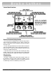
Safety Safety Notices and Decals For your safety, and the safety of others, read and understand all of the safety notices and decals included here and on the unit. Read entire manual before installing, operating, or servicing this equipment. Proper maintenance and inspection is necessary for safe operation. Warning This equipment incorporates parts such as snap switches and power receptacles which tend to produce arcs or sparks.
Safety Owner’s Responsibility Definitions of Hazard Levels To maintain machine and user safety, the responsibility of the owner is to read and follow these instructions: Identify the hazard levels used in this manual with the following definitions and signal words: • Follow all installation instructions. DANGER • Make sure installation conforms to all applicable Local, State, and Federal Codes, Rules, and Regulations; such as State and Federal OSHA Regulations and Electrical Codes.
IMPORTANT SAFETY INSTRUCTIONS Before operating the lathe, review the warning information on the lathe and the cautions, warnings and dangers in this manual. Also review the following general safety instructions. Failure to follow safety instructions could result in personal injury to operator or bystanders and damage to the lathe or personal property. READ ALL INSTRUCTIONS When using your garage equipment, basic safety precautions should always be followed, including the following: 1.
Brake Lathes Installation Receiving The shipment should be thoroughly inspected as soon as it is received. The signed bill of lading is acknowledgement by the carrier of receipt in good condition of shipment covered by our invoice. If any of the goods called for on this bill of lading are shorted or damaged, do not accept them until the carrier makes a notation on the freight bill of the shorted or damaged goods. Do this for your own protection.
Brake Lathes Electrical Wiring Requirements The lathe is factory wired to a disconnect box which should be grounded to the power supply box in accordance with local code requirements to protect the operator from shock. The lathe is grounded to the disconnect box through the flexible conduit. The flexible conduit should not be removed or eliminated. This box is to be mounted to the wall behind the machine.
Brake Lathes Lathe Operation Operating Specifications Overall Lathe Height . . . . . . . . . . . . . . . . . . . . . . .57in. (1447.8 mm) Spindle To Floor . . . . . . . . . . . . . . . . . . . . . . . . . .39 In. (990.6 mm) Turning Travel . . . . . . . . . . . . . . . . . . . . . . . . . . . . .18 In. (457.2 mm) Facing Travel . . . . . . . . . . . . . . . . . . . . . . . . . . . . . .7 In. (177.8 mm) Spindle Speed, Infinitely Variable . . . . . . . . . . . . . . . . .
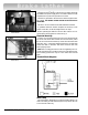
Brake Lathes Control Panel Functions Electrical Overload Safety Breaker The control panel is equipped with an overload safety breaker switch which will automatically turn the lathe off when the motor is overloaded or when something is wrong in the lathe’s electrical circuit. To reset, wait approximately three minutes before moving the switch to its RESET position. If the overload safety breaker continues to open, or if the line fuses are blown, have the circuit checked by a qualified electrician.
Brake Lathes Saddle and Cross Slide Locks The red handled saddle locks and cross slide locks tighten in a clockwise direction. Use the locks to maintain a constant depthof-cut when machining drums (saddle locks) and turning rotors (cross slide locks). Never engage a feed gearbox when its saddle or cross slide is locked, Fig. 1. Feed Gearbox Engagement Levers Each gearbox is labeled to indicate the ENGAGE and DISENGAGE positions.
Brake Lathes Gearbox Function & Handwheel Operation 6 • AMMCO 6000, 6002 Brake Lathes
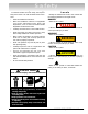
Brake Lathes Typical Drum Mounting Large Truck Drum Mounted On 2 1/2" Arbor A — Arbor B — Arbor Nut C — Arbor Washer D — Spacers E — Centering Cones Used As Spacers F — Centering Cones G — Lathe Spindle H — Draw Bar Floating Type Drum Mounted On 1 7/8" Arbor A — Arbor B — Arbor Nut C — Spacers D — Clamping Cups E — Centering Cone F — Spring G — Lathe Spindle H — Draw Bar Hub Type Drum Mounted On 1" Arbor A — Arbor Nut B — Arbor C — Self-Aligning Spacer D — Radii Adapters E — Lathe Spindle F — Draw Bar Hub
Brake Lathes Brake Drum Reconditioning Although drum turning is usually done on the right side of the lathe, the left side may also be used by turning the boring bar upside down in the left hand boring bar clamp. The following description assumes right hand operation: 1. Measure the diameter of the drum with a brake drum micrometer. If the drum diameter will be larger than the manufacturer’s specified rebore limit after machining, it must be replaced. Be sure the general condition of the drum is good. 2.
Brake Lathes Note: A “scratch” cut should be no more than .001" deep. If the “scratch” cut is too deep it will show a continuous line on the face of the drum and the runout will not be apparent. Back the tool bit off, stop the lathe, and check the mounting as follows: A. Loosen the arbor nut and rotate the drum one-half turn (180º) on the adapters. Note: The adapters must be held to keep them from turning. Retighten the arbor nut, turn the lathe ON, and make a second “scratch” cut. Turn the lathe OFF. B.
Brake Lathes Note: FEED AND SPEED SETTINGS—The following spindle speed and feed speed recommendations are intended to serve as a starting point for a machine operator not familiar with the lathe. Drums Up To 12" Dia. Over 12" Dia. Spindle Speed Medium Fast Medium Feed Speed Medium Slow Medium Slow Note: See CONTROL PANEL FUNCTIONS. Although these settings are relatively slow, they should give the manufacturer’s recommended finish and good tool life.
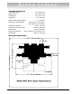
Brake Lathes Typical Rotor Mounting Large Truck Rotor Mounted On 2 1/2" Arbor A — Arbor B — Arbor Nut C — Arbor Washer D — Spacers E — Centering Cones Used As Spacers F — Centering Cones G — Lathe Spindle H — Draw Bar Hub Type Rotor Mounted On 1" Arbor A — Arbor Nut B — Arbor C — Self-Aligning Spacer D — Radii Adapters E — Lathe Spindle F — Draw Bar AMMCO 6000, 6002 Brake Lathes • 11
Brake Lathes Brake Rotor Reconditioning Each brake rotor should be carefully inspected for scoring, hard spots, and rust ridges at the inner and outer circumferences of the rotor. Any excessive wear or deformity should be noted and, the rotor should be replaced if not within acceptable limits. The twin cutter is designed to be used on the left cross slide in place of the boring bar clamp, to refinish both sides of a rotor at the same time.
Brake Lathes adjustable stop depresses the microswitch plunger. Tighten the lock screw to hold the stop at this point. 9. Advance the tool bits to the approximate center of the rotor faces. Turn the red and blue depth-of-cut knobs clockwise, one at a time, until their respective tool bits make light contact with the rotor face, making a “scratch” cut, Fig. 7. Note: A “scratch” cut should be no more than .001" deep.
Brake Lathes Maintenance and Service Oiling 2 3 1 4 The lathe is initially greased and the bare metal parts are coated with an oil-soluble rust preventative at the factory. It is not necessary to clean the rust preventative from these parts. Before using the lathe, however, all bare metal parts (ways, spindle, cross slides, etc.) should be wiped down with an oiled rag. Use a light machine oil or way oil for the initial wipe down and daily when oiling the bare metal parts.
Brake Lathes Care of Arbors and Adapters CAUTION Although the adapters, arbors, and the spindle are made of top grade steel and are turned, hardened, and precision ground to close tolerances, great care should be taken in their use, handling, and storage. Even the smallest nick, scratch, or loose chip can cause incorrect rotor or drum alignment and the result will be inaccurate machining. Always inspect the faces and the seating tapers of each adapter. Wipe each adapter clean before and after use.
Brake Lathes Drive Belt Replacement When replacing drive belts, the following procedure must be followed: 1. Turn the wall switch OFF. 2. Remove the arbor and drawbar from the spindle. 3. Remove the upper and lower belt guards. 4. Remove the spindle pulley and the spindle belt. 5. Remove the counter shaft bushing and the counter shaft belt. 6. Remove the access door, then the motor pulley and the motor belt. To remove the motor pulley: a. Remove both set screws. b.
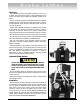
Brake Lathes Feed Motor Brush Replacement 1. Turn the wall switch OFF. Remove the motor cover and disconnect the electrical connector. 2. Unscrew the brush retaining plugs from the motor and remove the brushes. Note how the brushes are positioned in the motor, Fig. 6. 3. Install the new brushes so they contact the commutator correctly. 4. Replace the retaining plugs, connect the electrical wires, and replace the motor cover.
921657 18 06/01 © Copyright 1993 Hennessy Industries and AMMCO All Rights Reserved Printed in USA