
Owner's manual

Brake Rotor Reconditioning
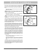
Each brake rotor should be carefully inspected for scoring,
hard spots, and rust ridges at the inner and outer circumfer-
ences of the rotor. Any excessive wear or deformity should be
noted and, the rotor should be replaced if not within acceptable
limits. The twin cutter is designed to be used on the left cross
slide in place of the boring bar clamp, to refinish both sides of a
rotor at the same time. The cross slide centers the twin cutter
to the rotor and the saddle feeds the twin cutter out when cut-
ting.
1. Use a micrometer to check the thickness of the rotor at
three or more points around the circumference and about 1"
(2.54 cm) in from the outer diameter. If the thickness is less
than specified by the manufacturer at any point measured, or
will be less after machining, the rotor should be replaced.
2. Before mounting a hubbed rotor inspect the bearings and
races for wear. Check a sample of lubricant from the bearings
for metal particles. An abundance of shiny metal chips indicates
a damaged bearing. Install a new bearing race before machining
the rotor. Also, check the hub for a loose race. If the bearing race
can be turned by hand the race recess is worn. Replace the hub
or hub and rotor. New bearing races are usually installed in the
hub during manufacturing. Be sure the races are fully seated in
the hub. New bearings should be used with new races.
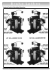
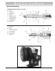
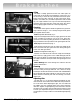
3. Mount the rotor on the arbor using the appropriate
adapters, cones and spacers. See the TYPICAL ROTOR
MOUNTING illustrations.
4. Install a silencer band by stretching it around the rotor and
hooking the wire loop over a lead weight.
5. Center the twin cutter to the rotor by manually moving the
cross slide forward or back so the rotor is evenly spaced
between the tool bits. Lock the cross slide in place.
6. Unlock the twin cutter tool slides and adjust them so they
are equally spaced from the center of the rotor.
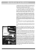
7. Loosen the boring bar clamp nuts of the twin cutter and
position the boring bars so approximately one-half of their
length is forward of the clamp studs. Manually advance the sad-
dle until the outer boring bar tool bit comes in contact with the
hub at the face of the rotor. Be sure the rotor has clearance with
the body of the twin cutter in this position. Wrench tighten the
outer clamp nut. Position the inner boring bar so its tool bit is
approximately 1/2" beyond the rotor face and wrench tighten its
clamp nut. Lock the tool slides in these positions. Be sure the
tool bits are not in contact with the rotor.
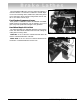
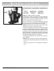
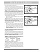
8. Set the saddle travel limit switch by either estimating the
travel necessary to cut the full width of the rotor faces or, if cut-
ting several rotors having the same outside diameter, crank the
saddle out so the tool bits are 1/4" to 1/2" outside the rotor. Be
sure all feed gearbox levers are in the DISENGAGE position.
Slide the adjustable travel limit stop against the microswitch
plunger, Fig. 6. The feed motor will shut off as the ramp of the
Brake Lathes
12 • AMMCO 6000, 6002 Brake Lathes
Figure 6 - Setting Limit Switch For Face Cut
Clearance
Adjustable Travel Limit Stop
Microswitch Plunger