
User guide

928365-1, 928529-1
Lead Screw Nut Replacement Kit
Installation Instructions for Models 4000, 4100 and 7500
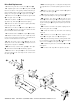
Exploded View Drawing Used for Reference
Installation Instructions
1. Turn the power to machine off.
2. Place shifter handle on gear case cover into
slow feed position and hold it in place.
3. Turn handwheel at least 10 turns counterclock-
wise to disengage coupler from lead screw .
4. Continue turning handwheel counter-clockwise
until cross feed no longer feeds out of or away from
the frame.
5. Remove 4 bolts holding gear case to the
frame of the lathe.
6. Remove gear case from the frame.
7. The lead screw nut (part no. 910868) can now
be replaced with the lead screw nut supplied in the kit
(ref. 3 above, part no. 928366).
8. Remove 2 socket head cap screws and 2 lock
washers securing the lead screw nut to the gear
case housing. Remove the lead screw nut.
9. Attach the new lead screw nut from the kit with
the new lock washers (ref. 4 above, part no. 903910)
and new cap screws (ref. 5 above, part no. 922585) by
reversing the procedure described in step 8.
Note: For Model 4000 with a serial number smaller
than 67028 and for a Model 4100 with a serial number
smaller than 6644, skip ahead to the next section, Drive
Rod Replacement. Otherwise, continue with step 10.
10. Mount the gear case to the frame with the 4
bolts .
11. Align the right angle drive mechanism with
the large pulley on the back of the frame by rotating the
gear case . The amount of rotation is limited by the
mounting bolts .
12. Tighten 4 mounting bolts .
13. Crank the handwheel clockwise to engage
the crossfeed with the gear case . A slight push on
the crossfeed toward the lathe frame may be neces-
sary to start the engagement.
14. Place the shifter handle on the gear case
cover into the slow feed position.
15. Remove the plastic cap , if not already
removed, and insert a 10" long, 1/2" drive socket exten-
sion into the tube protruding from the back of the gear
case cover .
16. Exert light pressure on the screw , inside the
tube, in the direction of the lathe frame. Continue to
apply light pressure.
17. Turn the handwheel slowly counterclockwise
a few turns to locate the lead threads on the coupler
with the lead screw . Then turn the handwheel M
clockwise to engage the threads.
18. The drive socket extension can be removed at
this time, and the plastic cap can be placed back on
the tube.
19. Tighten the lead screw into the coupler by
continuing to turn the handwheel clockwise while
holding the shifter handle in the slow feed position.
20. Loosen 2 guide bar set screws , move the
guide bar toward the front of the machine approxi-
mately 1/4", and retighten set screws .
*
*
*
*Included in kit
928365-1 only.
Parts Identification
ITEM PART NO. QTY. DESCRIPTION
1 940717 1* Coupler
2 910340 1* Drive Rod
3 928366 1 Lead Screw Nut
4 903910 2 Lock Washer
5 922585 2 Cap Screws
6 940403 1* Spring Pin