
User guide
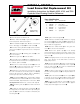

Drive Rod Replacement
1. Remove 4 gear case cover bolts (2 and 2 ).
2. Separate gear case cover from gear case .
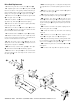
Note the locations of the gearing shafts and bushings.
Care should be taken to prevent these assemblies from
falling out of the gear case or gear case cover .
3. Remove 2 screws which retain the gear holder
in the gear case cover .
4. Remove plastic cap , drive rod retaining screw
, washer , and spring . Discard the spring.
5. Remove the drive rod and coupling assembly
from the gear case cover .
6. Remove the drive rod and coupler from the
drive gear , being sure to locate and save both drive
pins T and both thrust washers .
7. Discard the drive rod and coupler assembly.
8. Attach new drive rod to the new coupler by insert-
ing the end of the drive rod with the cross drilled hole
into the non-threaded end of the coupler.
9. Align the holes in the coupler with the cross
drilled hole in the new drive rod , and tap in the new
spring pin (ref. 6, part no. 940403).
10. Generously coat the drive gear , 2 drive pins
, and 2 thrust washers with bearing grease.
11. Place the 2 drive pins into the semi-circular
grooves located on the outer edge of the center hole in
the drive gear .
Note: The bearing grease on each part should provide
enough adhesion to hold the parts together for assem-
bly.
12. Place 1 each of the 2 thrust washers against
each side of the drive gear .
13. Noting the position of the 2 drive pins , lower
the drive gear assembly into the gear holder .
14. Slide the new drive rod through the rear
holder and the drive gear , orienting the key slots
in such a way as to prevent the drive rod form dislodg-
ing the 2 drive pins being held in place by the bear-
ing grease.
15. Insert the new drive rod and coupling assem-
bly into the gear case cover .
16. Install the washer , and drive rod retaining
screw .
17. Install the 2 screws , which retain the gear
holder in the gear case cover , and tighten.
18. Align the bushings and the gearing shafts with
the counter bores in the gear case , and slide the gear
case cover cover onto the gear case .
19. Install the 4 gear case cover bolts (2 and 2 )
and tighten.
20. Continue with step 10 in the previous section.
928370 02 04/01 COPYRIGHT 1993 AMMCO TOOLS ALL RIGHTS RESERVED PRINTED IN U.S.A.