Responding to a Fire LoopSense Fire Alarm Control Panel (EN54.
Responding to a Fire Access Level 1 Indicators Controls DELAY ACTIVE OVERRIDE FIRE ZONE 1 SILENCE BUZZER The OVERRIDE key is pressed to override any delays to outputs Access Level 2 EVACUATE The EVACUATE key is pressed to turn ON all alarm devices. ALARMS SILENCE RESOUND The SILENCE/RESOUND key is pressed to silence any silence-able outputs that have been activated.
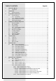
TABLE OF CONTENTS 1 2 3 4 5 6 7 Page No. About This Manual ............................................................................................................... 1 1.1 Introduction ................................................................................................................ 1 Introduction .......................................................................................................................... 1 2.1 System Overview ...........................................
8 7.2.3.4 Menu->Control->Panel->Loop............................................................... 25 7.2.3.5 Menu->Control->Panel->Printer ............................................................ 25 7.2.3.6 Menu->Control->Panel->Power ............................................................ 25 7.2.3.7 Menu->Control->Panel->Delay Mode .................................................... 26 7.2.4 Menu ->Control > Global Control ..................................................................
LOOPSENSE EN54 1 1.1 2 2.1 USER MANUAL About This Manual Introduction This manual contains all the information required to operate the LoopSense Fire Alarm Control Panel (FACP). The first step in becoming a proficient operator is to be familiar with and understand the “Menu Structure” and the keys used to navigate through it.
LOOPSENSE EN54 3 USER MANUAL Front Panel Control Card The Front Panel Control Card interfaces to the Main Control Board and supports; all the controls and functional indicators the FACP Reset Menu system control Serial or Parallel Printer port Figure 1: Front Panel Layout 3.1 Levels of Access The FACP supports three levels of access. Access Level 1 (Untrained User): The FACP is in Access Level 1 by default. Only the OVERRIDE, PREVIOUS, NEXT, SILENCE BUZZER and LAMP TEST controls are active.
LOOPSENSE EN54 3.1.1 USER MANUAL Passwords The FACP will support 99 user programmable passwords. Each password includes an access level which can be either 2 or 3 corresponding to the access levels and a unique ID which ranges from 1 to 99. There is also a facility in the access level 3 SETUP menu to add, edit or delete passwords. Note: Onsite programming only allows for the editing of ID1 and ID2 all other ID’s need to be 3.1.
LOOPSENSE EN54 3.2 USER MANUAL System Controls & Indicators The front panel has fourteen push button controls, a key switch and an alpha numeric keypad. Controls, Normal – Enabled (Key Switch) = OFF, = ON CONTROLS ENABLE KEY SWITCH. If the key switch is in the OFF position (access level 1), then the OVERRIDE, PREVIOUS, NEXT, SILENCE BUZZER and LAMP TEST controls are active.
LOOPSENSE EN54 USER MANUAL Previous Momentary push button. Used to scroll the LCD display to view the previous available entry. Fire Output / Next Available at access level 1 and above FIRE OUTPUT Fire Output – Illuminated steady if a designated fire output has been activated and flashes if a FARE input is configured and active and remains so until the fire alarm condition is reset. Next Momentary push button. Used to scroll the LCD display to view the next available entry.
LOOPSENSE EN54 USER MANUAL DISABLED EVACUATE Disabled – The indicator is illuminated when one or more zone detectors, loop devices or panel outputs are disabled. Evacuate - Momentary push button. Turns on all alarm devices, illuminates the FIRE indicator, activates the output to the fire alarm routing equipment and announces the evacuate condition on the LCD. Also if there any alarm devices configured with delays, the evacuate key will override these and force the alarm devices into evacuate.
LOOPSENSE EN54 USER MANUAL RN2 C1 RN1 C2 PARALLEL PRINTER R1 SERIAL Q2 R2 Q1 RN3 U2 U1 U3 R3 RN5 CN2 C3 LCD BACK LIGHT CN1 CN3 R6 R7 C4 R5 C5 RN4 R4 R8 C9 D35 R9 CN4 LCD CONNECTOR C8 Q3 D49 LK1 + U4 RN7 C10 Q5 U7 RN9 C13 D45 DISABLED FAULT TH1 C19 U10 D42 D43 U5 PRE-ALARM FIRE OUTPUT C26 CN6 RN8 D41 U8 C16 D40 RESET R15 DELAY ACTIVE C14 ALARMS RN12 Q6 FRONT PANEL I/F U9 D33 Q7 R20 R19 SW28 U11 C27 CN5 C17 R17 C20 R16 C22 R21 C25 C21 C23 C2
LOOPSENSE EN54 4 4.1 USER MANUAL Displayed Conditional Responses Normal Condition The POWER LED is illuminated meaning the mains voltage is present, and all other indicators are off. The 4 x 40 LCD will display the; current date, time and access level on line 1 configured user descriptors of customer/site specific information on lines 2 and 3 system status - day-night and manual I/O active information on line 4 In the above screen, ACCESS LEVEL corresponds to the currently active user access level.
LOOPSENSE EN54 4.2 USER MANUAL Fire Condition If an input or device is activated and it is configured to generate a fire condition the FACP responds to the fire as follows: Common FIRE LED will turn on steady Assigned zone fire LED will illuminate Panel buzzer will sound continuously Fire condition to be reported to the LCD (time ordered buffer 100 entries deep) The fire event will be logged and printed, where a printer is fitted.
LOOPSENSE EN54 4.3 USER MANUAL Fault Condition When the system registers a fault condition: Common FAULT LED will be illuminated Corresponding front panel fault LED will illuminate Assigned zone fault LED will flash Panel buzzer will sound intermittently Fault condition to be reported to the LCD. The fault event will be logged and printed, where a printer is fitted.
LOOPSENSE EN54 USER MANUAL Exception due to software failure in MTB – The system fault condition shall be hardware driven via software when panel reboots and can be silenced and cleared by pressing the STAR ‘*’ key on the FP provided the key-switch is in the access level 2 position. The exception codes shall be presented on the LCD for service support and the system shall remain in boot mode until resolved.
LOOPSENSE EN54 4.4 USER MANUAL Pre-Alarm Condition When a Pre-Alarm event occurs, the following actions take place. The associated LED will operate The condition will be reported on the LCD. The event will be logged and printed, where a printer is fitted. All outputs configured to operate under this condition will operate
LOOPSENSE EN54 4.8 USER MANUAL Disabled Condition When the user disables an input, output or zone the associated configured outputs will no longer operate and will no longer effect panel conditions. The system registers a disabled condition as follows: Common DISABLED LED will be illuminated Disabled condition to be reported to the LCD. The disable event will be logged and printed, where a printer is fitted.
LOOPSENSE EN54 5 5.1 5.2 USER MANUAL Test Functions The FACP provides a set of diagnostic test functions that can be run on various inputs & outputs (like loops, loop devices, LED indicators, LCD display, Sounders etc) to verify whether they operate as they are intended. The diagnostic test functions are; Loop test Lamp test Walk test Device Locator Loop Test Access level 2 - Control - Panel - Loop. - Test.
LOOPSENSE EN54 5.3 USER MANUAL Walk Test Access level 2 Walk Test and Silent Walk Test is available via the Menu - Control - Zone. - Select Zone - Silent Walk Test or - Walk Test The purpose of the walk test is to verify the detectors, MCP's and optionally the alarm devices (sounders) are functioning as required.
LOOPSENSE EN54 5.4 USER MANUAL Device Locator Access level 2 The Device Locator test is available via Menu - Control - Device - Select Device - Alarm led ON Device locator allows maintenance personnel to locate a particular device by forcing the device alarm LED ON. Only devices with physical alarm LED's support this test. This is a low priority test and can only be performed on one device at a time. Once invoked the user is prompted that the alarm LED has been forced on and to press CANCEL to end.
LOOPSENSE EN54 6 6.1 USER MANUAL Menu Structure Menu Layout and Navigation The main menu for the system is as shown below. The accessibility of this menu for the three access levels is as described previously and summarized below. Access Level 1: Menu not accessible Access Level 2: Menu partially accessible. The menu system is accessible except for the disablement of individual sounder devices, SETUP (*) and PROGRAMMING (*) menus, which are displayed with the suffix “(*)”.
LOOPSENSE EN54 6.1.1 6.1.2 USER MANUAL Generic Point Selection Screens Within the menu system there are several instances in which points are required to be selected in order to proceed further and display and/or manipulate the selected points. Points include Zones, Loops, Devices, Device Sub-Addresses, Panel Inputs, Panel Outputs and Add-Ons. Zone Point Selection Zones 1 up to 999 can be selected. SELECT ZONE: XXX ►Z1 Z2 Z3 Z4 Z6 Z7 Z8 Z9 6.1.
LOOPSENSE EN54 6.1.6 USER MANUAL Sub-Address Suffix: - Sub-Address Disabled Add-On Point Selection Add-On module addresses 1 up to 30 can be selected, depending on type. SELECT ADD-ON: XX ►A1 A2 A3 A4 A5 A6 A7 A8 A9 A10 6.1.7 Add-On Address Prefixes: A – Add-On configured X – Add-On not configured Add-On Address Suffix: * - Add-On Disabled Panel Input Point Selection Panel digital inputs 1 to 4 can be selected.
LOOPSENSE EN54 7 USER MANUAL Menu Structure & Navigation The following should be read in conjunction with the complete “Menu Structure”. The primary components of the Menu Structure are; DISPLAY CONTROL EVENTS TOOLS SETUP PROGRAMMING The sections below have been broken down by primary component for ease of explanation 7.
LOOPSENSE EN54 7.2 USER MANUAL Menu > Control Access Level 2 – to access this level the operator should use the “Controls Normal – Enable” keyswitch or enter the Password. NOTE: 2 ABC CONTROL 2 1 1 ZONE PANEL GHI 3 3 DEF 2 Pressing 2 ABC ABC 4 DEVICE 4 GLOBAL CONTROL 1: At Access Level 1, the entire menu is not accessible. 2: At Access Level 2, individual sounder disablement, SET-UP and PROGRAMMING menu items are not accessible, user can access level 3 via the correct password entry.
LOOPSENSE EN54 USER MANUAL ACTION: AVALUE:XXX I:000 O:000 DRIFT:YYY%MODE:X ◄BACK:DISABLE 2:SUB ADDR 3:PRINT 4:ALARM LED ON Note: Option 2 shall be SUB ADDR (Sub-Address) or REM O/P (Remote Output) depending on the type of device being displayed. Input Screens: Pressing DEVICE ► will also reveal the panel Input Control. Use the ▼▲ arrows to display the available panel inputs ACTION: ◄BACK 1:DISABLE 7.2.
LOOPSENSE EN54 USER MANUAL Non-Sounder Output Screens:
LOOPSENSE EN54 7.2.3.2 USER MANUAL Menu->Control->Panel->Output CONTROL PANEL OUTPUT MENU 1►SUPERVISED O/P 3|OPEN COLLECTOR O/P 2|RELAY O/P 4|AUXILIARY O/P 7.2.3.2.
LOOPSENSE EN54 USER MANUAL ◄BACK 1:DISABLE 2:I/O 3:PRINT Selecting “2:I/O” will display the individual inputs and/or outputs of the add-ons Use the ▼▲ arrows to display the available inputs and outputs Non-Sounder Outputs:
LOOPSENSE EN54 7.2.3.7 USER MANUAL Menu->Control->Panel->Delay Mode This menu is only accessible if investigation delays have been configured and the panel is in the day or night modes in which delays are configured. INVESTIGATION DELAY MODE: ON ◄BACK 7.2.
LOOPSENSE EN54 7.3.3 USER MANUAL Menu->Events->Goto GOTO EVENTS 1►MOST RECENT 2|BY DATE 3|BY ENTRY 7.4 Menu > Tools 4 GHI TOOLS 1 2 DIRTY DEVICES LOOP STATISTICS 1 2 LOW% 3 MED% 1 HIGH% 2 L1 L2 1 RESET COUNT TOOLS MENU 1►DIRTY DEVICES 2|LOOP STATISTICS 7.4.1 Menu->Tools->Dirty Devices The compensation threshold level can be set to the default Low, Medium or High percentage.
LOOPSENSE EN54 7.5 USER MANUAL Menu > Setup 5 JKL SETUP 1 DATE AND TIME 1 2 DATE 2 3 FORMAT 4 5 TIME DAYLIGHT SAVE ON/OFF FORMAT 3 DAY/NIGHT 1 EARTH MON 2 SUNDAY 3 MONDAY 4 TUESDAY 5 WEDNESDAY THURSDAY 6 7 FRIDAY SATURDAY 6 7 SET ALL DISABLE 4 PASSWORDS 1 2 ID1 ID2 SETUP MENU 1►DATE AND TIME 2|DAY/NIGHT 7.5.1 3|EARTH MONITORING 4|PASSWORDS This menu is only accessible at access level 3.
LOOPSENSE EN54 7.5.2.1 USER MANUAL Menu->Setup->Day/Night->Day DAY/NIGHT SETTINGS - SUNDAY CURRENT - DAY: HH:MM NIGHT: HH:MM NEW - DAY: _ NIGHT: DEL▲ ◄BACK APPLY▼ NEXT► 7.5.3 Back will return to day/night menu or previous day if not on first day selected. Next will proceed to the day/night settings for each of the remaining six days in sequence after which it will return to the day/night menu.
LOOPSENSE EN54 7.
LOOPSENSE EN54 USER MANUAL Use the alpha-numeric keys to key in descriptor characters. Pressing next (or enter) will update the programming.
LOOPSENSE EN54 USER MANUAL SELECT DEVICE TYPE: CHANGE▼ NEXT► ◄BACK 7.6.2.1 Menu->Programming->Device->Add In this wizard the user can scroll through the desired device type to be added. The user is also prompted to save changes if required. 7.6.2.2 Menu->Programming->Device->Delete Zzzz Ppp Lll Dddd.s ◄BACK DELETE► Once selected the device location and type shall be displayed: The user shall then be prompted to save changes if required. 7.6.2.
LOOPSENSE EN54 USER MANUAL Press CHANGE▼ to browse through the available latching state options. Press NEXT► to go to the next field. EDIT PRE-DELAY: 0 (0-90 seconds) DEL ▲ NEXT► #CLEAR ◄BACK Key-in the new pre-delay value for the selected field. Press NEXT► to go to the next field. DAY SENSITIVITY: 100 (80-120%) DEL ▲ NEXT► #CLEAR ◄BACK Press NEXT► to enter the sensitivity mode of the device.
LOOPSENSE EN54 USER MANUAL TYPE: 1 DEVICE 2►SUB ADDRESS NEXT► If the device type has sub-address inputs or outputs this screen is displayed next: SELECT SUB ADDRESS: 1 1►I/P1 2:I/P2 3:I/P3 4:O/P1 5:O/P2 6:O/P3 Select 2 SUB ADDRESS and pressing NEXT► displays the generic sub-address selection screen: EDIT DESCRIPTOR LOOP 1 DEVICE 1 INPUT 1_ #CLEAR ◄BACK DEL▲ NEXT► Select one of the sub inputs and press enter to edit the input configuration.
LOOPSENSE EN54 USER MANUAL EDIT DEVICE TYPE: CHANGE▼ NEXT► ◄BACK Once the device is selected firstly the device type can be changed: WARNING: SETTINGS WILL BE DEFAULT EXCEPT ZONE NUMBER AND DESCRIPTOR PROCEED WITH CHANGE ◄BACK 1:YES If the device type is changed this confirmation screen is displayed: TYPE: 1 DEVICE 2►SUB ADDRESS If the device type has sub-address inputs or outputs the following screen is displayed next: SELECT SUB ADDRESS: 4
LOOPSENSE EN54 USER MANUAL NORMALLY ENERGISED: DISABLED CHANGE▼ NEXT ► ◄BACK Press CHANGE▼ to enable or disable the displayed zone action. Press NEXT► to go to the next zone action setting. RESPOND TO ALERT/EVAC: ENABLED CHANGE▼ NEXT► ◄BACK Press NEXT► to go to the next field. RESPOND TO CLASS CHANGE: ENABLED CHANGE▼ NEXT► ◄BACK Press NEXT► to go to the next field. EDIT POST-DELAY: 0 (0-999 seconds) #CLEAR ◄BACK 7.6.3 Press NEXT► to go to the next field.
LOOPSENSE EN54 USER MANUAL EDIT ACTION TYPE: FIRE CHANGE▼ NEXT► ◄BACK Press NEXT► to go to the next field. INPUT TYPE: NON-LATCHING CHANGE▼ NEXT► ◄BACK Press NEXT► to go to the next field. EDIT CONTACT STATE: NORMALLY OPEN CHANGE▼ NEXT► ◄BACK Press NEXT► to go to the next field. SUPERVISED: ENABLED CHANGE▼ NEXT► ◄BACK Press NEXT► to go to the next field. EDIT PRE-DELAY: 0 (0-90 seconds) DEL ▲ NEXT► #CLEAR ◄BACK Press NEXT► to go to the next field.
LOOPSENSE EN54 USER MANUAL ENTER ZONE NUMBER: 1_ DEL ▲ NEXT► #CLEAR ◄BACK Press NEXT► to go to the next field. FIXED ACTIVATION: NONE CHANGE▼ NEXT► ◄BACK Press NEXT► to go to the next field. OUTPUT TYPE: SOUNDER CHANGE▼ NEXT► ◄BACK Press NEXT► to go to the next field. GLOBAL ACTION: ENABLED CHANGE▼ NEXT► ◄BACK Press CHANGE▼ to enable or disable the displayed global action. Press NEXT► to go to the next field.
LOOPSENSE EN54 USER MANUAL EDIT POST-DELAY: 0 (0-999 seconds) #CLEAR ◄BACK NEXT► Press NEXT► to go to the next field. The user is then prompted to save any changes that may have been made. 7.6.3.3 Menu->Programming->Panel->Loop SELECT LOOP: X ►L1 L2 If there is more then one loop the user is prompted to select the loop using the generic loop selection screen. EDIT DESCRIPTOR LOOP 1_ #CLEAR ◄BACK DEL▲ NEXT► Press enter to edit the selected Loop configuration settings.
LOOPSENSE EN54 USER MANUAL The activation mode choices are: EVACUATE ALERT ALERT TIMEOUT EVACUATE DELAYED GLOBAL ACTIVATION DELAY: 30 #CLEAR ◄BACK (0-999 Sec) NEXT► The activation mode screens are repeated for all action types in which the delays can be edited The user is then prompted to save any changes that may have been made. 7.6.4.
LOOPSENSE EN54 USER MANUAL AUTO LEARN CONFIGURATION WILL BE CHANGED ARE YOU SURE? ◄BACK 1:YES Select 1 to confirm. AUTO LEARN INITIALISING PLEASE WAIT ◄BACK NEXT► While the Auto Learn sequence is initialising all system functions cease, and the panel is prepared for Auto Learn. AUTO LEARN IN PROGRESS <-----> ◄BACK The Auto Learn in Progress screen is displayed while all devices have been learnt. Upon completion the panel will restart with the newly learnt configuration. 7.6.5.
LOOPSENSE EN54 USER MANUAL Zzzz Ppp Ll Dddd.s CONFIGURED TYPE: MISSING DEVICES XXX OF XXX ◄BACK 1:DELETE 2:DELETE ALL If no missing devices were detected the following screen is displayed for a short period before returning to the previous menu. NO MISSING DEVICES DETECTED 7.6.
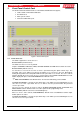
LOOPSENSE EN54 7.7 USER MANUAL Event Logging Events are logged into one of eight event type categories. Individual storage is pre-allocated for each event type amounting to a total of 1000 events: Event Type Fire Fault Disable Pre-Alarm Emergency Security User System Maximum Capacity 100 200 100 100 100 100 100 200 If an event exceeds the maximum capacity for that type the oldest event will be discarded allowing the most recent event to be stored.
LOOPSENSE EN54 8 INSTALLATION & COMMISSIONING Complete Menu Structure 1 DISPLAY 1 2 FIRE 2 3 FAULT 4 5 6 SECURITY PRE-ALARM EMERGENCY 8 7 USER 9 TEST DISABLE ABOUT CONTROL 2 1 ZONE DEVICE 2 1 3 DISABLE INPUTS DISABLE SOUNDERS 4 SILENT WALK TEST 1 DEVICE> WALK TEST INPUT 1 2 DISABLE DEVICE 3 DISABLE 1 PRINT ON 2 1 3 SUB ADDR / REM O/P NOTE: SUB ADDR AND REM O/P DEPEND ON THE SELECTED DEVICE DISABLE PRINT 1 SUB ADDR / REM O/P ALARM LED ON 2 DISABLE NOTE: SUB
0832 AMPAC Technologies Ltd 7 Ledgar Road Balcatta, Western Australia, 6021 09 0832-CPD-1288 EN54-2 & 4 1997 including amendments 1 & 2 Control and Indicating equipment and Power Supply equipment for fire detection and fire alarm systems for buildings 8281-0105 1 Loop 32 Zone analogue addressable control and indicating equipment 8281-0205 1 Loop 32 Zone analogue addressable control and indicating equipment Provided options: Output to fire alarm devices Output to fire alarm routing equipment Alarm confirmat