
Datasheet


BergStik
®
Unshrouded Stacking Headers
2.54 mm
13
Dimensions in mm
Technical / Application Support / Drawings / Specifications / Samples: www.fciconnect.com/basics
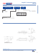
Part Number
Step-by-Step Design
1. Determine desired board spacing (0.50 mm increments)
2. Select Dubox™ receptacle and calculate stack height
Stack Height = Board Spacing – Receptacle Height
3. Find the insertion depth from the chart below.
Calculate max./min. OAL
OAL = Stack Height + solder side + Insertion Depth
4. Select the Pin Style with OAL between max.
and min. values
Example:
1. Application requires a board spacing of 22.50
2. Select the Dubox™ Low Profile Receptacle
with height of 7.00
The Header Stack Height is 22.50 - 7.00 = 15.50
3. For standard board applications, the
3.05 solder side is selected
OAL (max.) = 15.50 + 3.05 + 6.10 = 24.65
OAL (min.) = 15.50 + 3.05 + 3.86 = 22.41
4. Select Pin Style 08 with OAL = 23.50
5. Part Number is 54122-108-72-1550
1 = Single Row (TMT only)
2 = Double Row
1 = Through Hole (TMT)
2 = Surface Mount (SMT)
01 to 36 single row (TMT)
04 to 72 double row (TMT)
04 to 50 double row (SMT
XX.XX = mm
Specify mm
(i.e. 08.50 = 8.50 mm
in 0.50 mm increments
08.00 min. - 25.00 max.)
1 = 2.41
2 = 3.05
4 = SMT (double row only)
Pin OAL (TMT) OAL (SMT)
Style mm mm
01 12.20 10.42
02 13.50 11.72
03 15.90 14.12
04 16.76 14.98
05 17.65 15.87
06 18.91 17.13
07 20.96 19.18
08 23.50 21.72
09 26.04 24.26
10 28.58 26.80
11 31.12 29.34
12 33.66 31.88
5 4
Lead
Solder
Side
Option
Row
Option
Plating Pin Style
Total
Positions
Stack Height
Recommended PCB Layout
Dubox™ RECEPTACLES
Low Profile Vertical
Height 7.00 8.50
Insertion Depth (max.) 6.10 6.10
Insertion Depth (min.) 3.86 4.34
1 = 0.76 µ
m
gold on mating area, tin-lead on solder side
4 = 3.81 µ
m
tin-lead
8 = 0.38 µ
m
gold on mating area, tin-lead on solder side