Amphenol ® PT Series Miniature Cylindrical Connectors 12-022-18 www.amphenol-industrial.com Amphenol® 97 Series Connectors are UL recognized and CSA recognized.
Table of Contents Introduction, Amphenol® Miniature Cylindrical Page General Information, Design Flexibility . . . . . . . . . . . . . . . . . . . 1, 2 Connector Selection Guide . . . . . . . . . . . . . . . . . . . . . . . . . . 3 Insert availability . . . . . . . . . . . . . . . . . . . . . . . . . . . . . . . . . 4, 5 Alternate positioning . . . . . . . . . . . . . . . . . . . . . . . . . . . .
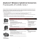
Amphenol ® Miniature Cylindrical Connectors Proprietary/MIL-DTL-26482, Series 1 Amphenol® Miniature Cylindrical connectors offer twice the number of contacts in just half the size of a Standard connector. These miniature connectors, are available in several series, each with varying design characteristics and customer options to meet cost considerations and provide maximum design flexibility.
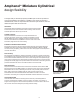
Amphenol® Miniature Cylindrical design flexibility The large family of miniature proprietary and MS style connectors provides for many optional features and designs. In addition to the choices of bayonet or threaded shells, solder or crimp termination within the style variations, there are additional options that are shown here. Hermetics Hermetically sealed receptacles have fused compression glass sealed inserts which provide envionrmental moisture sealing.
Amphenol® Miniature Cylindrical connector selection guide The accompanying chart is provided to assist the user in selecting the appropriate type of miniature connector to meet the application requirements. Further information can be found in specific sections of this catalog.
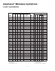
Amphenol ® Miniature Cylindrical insert availability Solder Termination Insert Arrangement MS/PT 6-1 Crimp Termination PT SP Hermetic PT MS-PT MS/PT-SE PT-SE SP-SE Contact Size Coax Total Contacts 20 16 12 12 8 Service Rating X X X* 1 1 I 8-2 X X X X 2 2 I 8-3 X X X X 3 3 I 8-4 X X X X 4 4 I 8-33 X X X X 3 3 I 8-98 X X 3 3 10-2 X X 2 10-5 X X X* X X X X X 10-6 X 10-70 X I 2 5 5 6 6 I I I 1 10-98 X X X X* 12-3
Amphenol ® Miniature Cylindrical insert availability, cont.
Amphenol ® Miniature Cylindrical alternate positioning A B A B Position W Position X 6 8 8 8 8 8 10 10 10 10 10 12 12 12 12 12 12 14 14 14 14 14 14 14 14 14 14 14 14 16 16 16 16 16 16 18 18 Insert Arrangement 6-1 8-2* 8-3 8-4* 8-33* 8-98 10-2 10-5* 10-6* 10-70 10-98* 12-3* 12-4* 12-8 12-10* 12-14 12-98* 14-2 14-4* 14-5* 14-8 14-12* 14-15* 14-18* 14-19* 14-22 14-71 14-91HV 14-AA* 16-8* 16-23 16-26* 16-70 16-76 16-99* 18-5 18-8 – 58 60 45 90 – 45 45 90 – 90 – 38 90 60 – 61 58 45 40 48 43
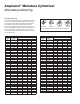
Amphenol ® Miniature Cylindrical insert arrangements front face of pin inserts illustrated C A B Insert Arrangement Service Rating Number of Contacts Contact Size 6-1 I 1 20 E D 8-2 I 2 20 Insert Arrangement Service Rating Number of Contacts Contact Size 10-5 I 5 20 G K F Insert Arrangement Service Rating Number of Contacts Contact Size A J C J E D 12-10 I 10 20 H G J B K F E L C D 14-12 I 8 4 20 16 E K N P K J L A M R H F B D F E 14-15 I 14 1 20 16 A C G D H E
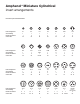
Cylindrical Amphenol ®® Miniature Cylindrical insert arrangements front face of pin inserts illustrated A A D L H C C E 14-AA 16-8 Number of Contacts 4 8 I Contact Size A N J L P H P B N C M D M G L E Number of Contacts Contact Size 16-76 8 5 20 12* 2 Coax* 21 20 Y K I W X J 16-23 H E J E G 20 N/A 20 V E D A H F C B K H C 1 12 Coax J B B D L 14 G E D K 16-70 26 16 C R M F I 1 B N F 16-26 A C U L G C F G I L E V H
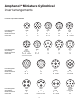
Cylindrical Amphenol ®® Miniature Cylindrical insert arrangements front face of pin inserts illustrated L A K L B M K N S C J H D H G F a T G S 20-25 Number of Contacts 16 24 25 I 16 N b L c X K R P F H 20-27 Number of Contacts 27 i g k Z m q d e M L b c H J K U D F g R f P N 20-39 37 20 I 20 p e d F 10 C P X D U J 20-90 Number of Contacts J F 7 21 25 8 Coax N M A P a B j g Z K C d D e f Y T P N k H W G V F E
Cylindrical Amphenol ®® Miniature Cylindrical insert arrangements front face of pin inserts illustrated k R m j N i B V n X q BB HH y FF DD h L w v f e Insert Arrangement 22-55 Number of Contacts 55 Service Rating E T K N G R H E F 22-70 13 20 2 8 Coax N B F Y K a J b g c d C H Insert Arrangement 22-78 22-96 24-31 Number of Contacts 7 7 31 Coax 8 Coax W v GG s r U q T PP MM EE p S LL DD n R P CC BB m k N M 24-61 Number of Contacts
Amphenol® PT, SP, MS/PT Proprietary/MIL-DTL-26482, Series 1 bayonet coupling and solder termination wall mounting receptacle cable connecting receptacle* Amphenol® solder contact miniature cylindrical connectors meet the most critical application needs. Design versatility combined with high reliability performance makes these series of Miniature Cylindrical Connectors ideal for environmental sealing or pressurized applications.
PT, SP Service Classes PT and SP connectors are available in the service classes listed below. Each class, with the exception of hermetic, offers one or more means of terminating or supporting a cable or wire bundle. “A” “A” general duty General duty; back shell is threaded for con duit attachment of MS3057 cable clamp “A” (SR) General duty, with strain relief clamp for cable or wire bundle support “C” “E” Pressurized receptacle; less than 1 cu. in.
PT00 (MS3110) SP00 wall mounting receptacle S R PT .120 ± .005 Dia. (.147 ± .005 Dia., size 24) SP .150 ± .005 Dia.
PT01 (MS3111) cable connecting receptacle L S Y S Q M A “PG” Cable Gland Seal K TERMINATION ASSEMBLIES “A” General Duty “A” (SR), “E” (SR), “P” (SR), MS / “F” Strain Relief L N Z “E” Open Wire Seal L V L “P” Potting Boot N L L PT01PG-XX-XXX D GD H N N N D “J” Cable Seal XL C .375 MIN PURCHA PT01A-XX-XXX (SR) PT01E-XX-XXX (SR) PT01P-XX-XXX (SR) MS3111F-XX-XXX PT01A-XX-XXX PT01E-XX-XXX MS3111E-XX-XXX PT01P-XX-XXX MS3111P-XX-XXX N Recept.
PT02 (MS3112) SP02 box mounting receptacle S R (TP) PT .120 ± .005 Dia. (.147 ± .005 Dia., size 24) L M SP .150 ± .005 Dia. R S (TP) 4 Holes A N K Z PT02A-XX-XXX SP02A-XX-XXX * PT02C-XX-XXX * SP02C-XX-XXX * PT02E-XX-XXX * SP02E-XX-XXX MS3112E-XX-XXX * PT02P-XX-XXX * SP02P-XX-XXX MS3112P-XX-XXX To complete part number see how to order on page 25. n (MMC) located within .
PT06 (MS3116) SP06 straight plug S L J Z Q “PG” Cable Gland Seal “A” General Duty L “A” (SR), “E” (SR), “P” (SR), MS / “F” Strain Relief “E” Open Wire Seal L V N L TERMINATION ASSEMBLIES D “P” Potting Boot L L GDH N N N N D D PT06PG-XX-XXX SP06PG-XX-XXX PTG06PG-XX-XXX C .
PT07 (MS3114) SP07 jam nut receptacle S H M S “A” General Duty/ “C” Pressurized Receptacle PT07A-XX-XXX PT07C-XX-XXX J A R M Z N P Shell Size 6 8 10 12 14 16 18 20 22 24 H ±.016 .625 .750 .875 1.062 1.188 1.312 1.438 1.562 1.688 1.816 Shell C Size Thread 6 8 10 12 14 16 18 20 22 24* – 6-32 6-32 6-32 6-32 6-32 8-32 8-32 8-32 8-32 S .812 .938 1.062 1.250 1.375 1.500 1.625 1.812 1.938 2.062 .348 .473 .590 .750 .875 1.000 1.125 1.250 1.375 1.500 J Flat +.000 –.010 .405 .530 .655 .818 .
PT08 E SP08 E 90 degree plug G “E” Open Wire Seal, “E” (SR) Strain Relief TERMINATION ASSEMBLIES “P” Potting Boot 75 degrees L L E A B PT08E-XX-XXX SP08E-XX-XXX PT08E-XX-XXX (SR) SP08E-XX-XXX (SR) H PT08P-XX-XXX SP08P-XX-XXX D K C To complete part number see how to order on page 25. All lockwire holes are .044 Dia. Min. Plug Front View Plug Side View Class “E”, “E” (SR) B ±.031 C +.010 –.025 .796 .655 10 .921 12 1.046 14 Class “P” D ±.062 E +.047 –.025 L ±.057 A ±.025 H ±.
PT Connectors with Printed Circuit Board Contacts S R 4 HOLES .120 ± .005 Dia. (.147 ± .005 Dia., size 24) (TP) Box Mounting Receptacle (PT02) with PCB Contacts R S Shell Size 71-570121-XXX 6 71-570120-XXX 10 71-570122-XXX 8 12 14 16 18 20 22 24 R (TP) K +.021 –.010 L Max. M +.010 –.000 N Dia. Max. Z +.040 –.050 .594 .812 .473 .493 .825 .431 .449 .380 .688 .938 .969 1.219 1.000 1.438 1.250 1.062 71-570128-XXX 1.250 1.125 1.312 1.156 71-570129-XXX .590 1.
PTB SPB thru bulkhead receptacle S R PTB .120 ± .005 Dia. (.147 ± .005 Dia., size 24) SPB .150 ± .005 Dia. (TP) R S 4 Holes P M L A A (TP) K * PTB-XX-XXX * SPB-XX-XXX * To complete part number add desired arrangement number (refer to pages 4 and 5 for insert availability) and add “PS”; Example: PTB-18-32PS. If a rotation is required, use PTB-18-32PS and add W, X, Y or Z. Example: PTB-18-32 PSW. The socket end of the insert always appears at the “P” dimension end of shell.
PT hermetic Three shell styles are available in the hermetic PT bayonet series: • PTIH (MS3113H) • PT02H • PT07H (MS3114H) These hermetic connectors are only available with solder cup or flat eyelet pin contacts in the MS/PT version. Socket contacts are available in some proprietary PT versions. Other design characteristics of the PT hermetic connector series are as follows: Shell sizes: 8 through 24 (tin plated) solder mounting receptacle Contact count: 2 through 61.
PTIH (MS3113H) hermetic solder mounting receptacle L G W A N .031 +.006 –.005 * ** ** † †† †† Z PTIH-XX-XXX PTIY-XX-XXX MS3113H-XXCXXX PTIH-XX-XXX (100) PTIY-XX-XXX (100) MS3113H-XXYXXX To complete part number see how to order on page 25. * Solder cup pin contacts without interfacial seal ** Solder cup pin contacts with interfacial seal † Flat eyelet pin contacts without interfacial seal †† Flat eyelet pin contacts with interfacial seal Recept. Front View Receptacle Side View G Dia. Max. A Dia.
PT02H hermetic box mounting receptacle PT .120 ± .005 Dia. (.147 ± .005 Dia., size 24) S R (TP) L W SP .150 ± .005 Dia. R S 4 Holes A (TP) N U * ** † †† Z PT02H-XX-XXX PT02Y-XX-XXX PT02H-XX-XXX (100) PT02Y-XX-XXX (100) To complete part number see how to order on page 25.
PT07H (MS3114H) hermetic jam nut receptacle S H M S Z A R * ** ** † †† †† P K PT07H-XX-XXX PT07Y-XX-XXX MS3114H-XXCXXX PT07H-XX-XXX (100) PT07Y-XX-XXX (100) MS3114H-XXYXXX To complete part number see how to order on page 25. * Solder cup pin contacts without interfacial seal ** Solder cup pin contacts with interfacial seal † Flat eyelet pin contacts without interfacial seal †† Flat eyelet pin contacts with interfacial seal Receptacle Front View Receptacle Side View Shell Size S +.016 H Hex +.
PT, SP, MS/PT how to order PT, SP To more easily illustrate ordering procedure, part number PT00A-20-41PW(SR) is shown as follows: PT 00 A - 20 - 41 P W (SR) 1 2 3 4 5 6 7 8 See code below: 1.
Amphenol PT-SE, SP-SE, MS/PT-SE Proprietary/MIL-DTL-26482, Series 1 bayonet coupling and crimp termination Amphenol® SE crimp type miniature connectors provide performance and versatility needed for applications demanding high reliability and crimp removable contacts. These crimp contacts are rear insertable/front release and are held in position by an MS approved spring tower retention system.
PT-SE. SP-SE, MS/PT-SE Contact Specifications Test Current Maximum Millivolt Drop† Crimp Well Diameter Minimum Well Depth 20 7.5 55 .049 ±.001 .267 16 13.0 49 .067 ±.001 .236 12 23.0 42 .100 ±.002 .236 Contact Size “SE”, MS / “E” open wire seal Service Rating Recommended Operating AC Voltage at Sea Level Sea Level 50,000 ft. I 600 1,500 500 375 200 II 1,000 2,300 750 500 200 Service Rating Test Voltage AC (RMS), 60 cps 70,000 110,000 ft. ft.
PT00 SE (MS3120) SP00 SE wall mounting receptacle S R T Dia. 4 Holes (TP) R S (TP) TERMINATION ASSEMBLIES “SE” Open Wire Seal “SE” (SR), MS / “F” Strain Relief L L M A L K A N M “SP” Potting Boot G A N K D N M PT00SE-XX-XXX SP00SE-XX-XXX MS3120E-XX-XXX PT00SE-XX-XXX (SR) SP00SE-XX-XXX (SR) MS3120F-XX-XXX K PT00SP-XX-XXX SP00SP-XX-XXX To complete part number see how to order on page 36. n (MMC) located within .
MF00 SE (MS3128) wall mounting receptacle T¹ Dia. 4 Holes S R¹ (TP) R (TP) R R¹ (TP) (TP) S T Dia. 4 Holes TERMINATION ASSEMBLIES MS / “E” Open Wire Seal L L K M N A M MS / “F” Strain Relief A K MF00SE-XX-XXX MS3128E-XX-XXX GF N MF00SE-XX-XXX (SR) MS3128F-XX-XXX To complete part number see how to order on page 36. n (MMC) located within .0025 of (TP) Receptacle Front View Shell Size Receptacle Side View Class MS / “E” Class MS / “F” T Dia. ±.005 T1 Dia. ±.005 A Dia. +.001 –.
PT01 SE (MS3121) SP01 SE cable connecting receptacle S S TERMINATION ASSEMBLIES “SE”, MS / “E” Open Wire Seal “SE” (SR), MS / “F” Strain Relief “SP”, MS / “P” Potting Boot L L A N A L K G K PT01SE-XX-XXX SP01SE-XX-XXX MS3121E-XX-XXX D N A N K PT01SE-XX-XXX (SR) SP01SE-XX-XXX (SR) MS3121F-XX-XXX PT01SP-XX-XXX SP01SP-XX-XXX MS3121P-XX-XXX Note: This connector style is sometimes referred to as a cable connecting “plug”. It does, however, mate with either a straight or 90 degree plug.
PT02 SE (MS3122) SP02 SE box mounting receptacle S L R M (TP) R S (TP) K A T Dia. 4 Holes N D PT02SE-XX-XXX SP02SE-XX-XXX MS3122E-XX-XXX To complete part number see how to order on page 36. n (MMC) located within .0025 of (TP) Receptacle Front View Receptacle Side View T Dia. ±.005 PT SP K ±.016 L Max. PT SP .473 .312 – .062 1.296 .431 – .438 .150 .590 .312 .219 .062 1.296 .431 .462 .562 .150 .750 .312 .219 .062 1.296 .431 .462 .688 .120 .150 .875 .312 .
MF02 SE (MS3127) box mounting receptacle T¹ Dia. 4 Holes S R¹ L (TP) M R (TP) R R¹ (TP) (TP) S K A T Dia. 4 Holes N D MF02SE-XX-XXX MS3127E-XX-XXX To complete part number see how to order on page 36. n (MMC) located within .0025 of (TP) Receptacle Front View Shell Size N Dia. +.011 –.000 Receptacle Side View S Max. T ±.005 T1 ±.005 A Dia. +.001 –.005 D Max. K ±.016 L Max. M +.010 –.000 R R 10 .562 .719 .812 1.141 .120 .150 .590 .219 .062 1.266 .462 12 .688 .812 .
PT06 SE (MS3126) SP06 SE straight plug S TERMINATION ASSEMBLIES “SE”, MS / “E” Open Wire Seal “SE” (SR), MS / “F” Strain Relief L “SP”, MS / “P” Potting Boot L L N G N Z pin contacts Z¹ socket contacts D N Z pin contacts Z¹ socket contacts PT06SE-XX-XXX SP06SE-XX-XXX PTG06SE-XX-XXX MS3126E-XX-XXX Z pin contacts Z¹ socket contacts PT06SE-XX-XXX (SR) SP06SE-XX-XXX (SR) PTG06SE-XX-XXX (SR) MS3126F-XX-XXX PT06SP-XX-XXX SP06SP-XX-XXX PTG06SP-XX-XXX MS3126P-XX-XXX To complete part number see how
PT07 SE (MS3124) SP07 SE jam nut receptacle S H S TERMINATION ASSEMBLIES “SE”, MS / “E” Open Wire Seal M “SE” (SR), MS / “F” Strain Relief L M K R “SP”, MS / “P” Potting Boot L M K K N J A F N J A PT07SE-XX-XXX SP07SE-XX-XXX MS3124E-XX-XXX G N J A R P P L R P PT07SE-XX-XXX (SR) SP07SE-XX-XXX (SR) MS3124F-XX-XXX PT07SP-XX-XXX SP07SP-XX-XXX MS3124P-XX-XXX To complete part number see how to order on page 36. All lockwire holes are .044 Dia. Min.
PT08 SE SP08 SE 90 degree plug G TERMINATION ASSEMBLIES “SE” Open Wire Seal, “SE” (SR) Strain Relief “SP” Potting Boot 75 degrees L L E A B PT08SE-XX-XXX SP08SE-XX-XXX PT08SE-XX-XXX (SR) SP08SE-XX-XXX (SR) H D K PT08SP-XX-XXX SP08SP-XX-XXX C To complete part number see how to order on page 36. All lockwire holes are .044 Dia. Min. Plug Front View Plug Side View Class “SE”, “SE” (SR) G Dia. Max. B ±.031 C +.010 –.025 10 12 .921 .749 1.046 .812 14 16 1.171 1.297 18 1.
PT-SE, SP-SE, MS/PT-SE how to order PT-SE, SP-SE To more easily illustrate ordering procedure, part number PT00SE-2041PW(SR) is shown as follows: PT 00 SE - 20 - 41 P W (SR) 1 2 3 4 5 6 7 8 See code below: 1.
PT & SP accessories – sealing plugs, flange gaskets, potting boots SEALING PLUGS – FOR PT & SP C B DIA .135 +.030 –.025 A DIA Contact Size 12 16 20 Amphenol® Part Number A Dia. ±.010 MS Number 10-405996-12 MS27488-12 10-405996-16 MS27488-16 10-405996-20 MS27488-20 B Dia. ±.005 .121 .083 .060 .171 .133 .090 C ±.010 .564 .564 .564 Color Code Yellow Blue Red How to Order: Order by 10- (Proprietary) or MS part number as shown in chart above.
PT & SP accessories – clamps CLASS “E” STRAIN RELIEF CLAMP – FOR PT & SP Shell Size L B 8 10 12 14 16 18 20 22 24 D G C CLASS “E” STRAIN RELIEF CLAMP 10-101971-XX B Max. C Thread Class 2B .550 .675 .803 .920 1.047 1.165 1.291 1.418 1.533 6-32 NC 6-32 NC 6-32 NC 6-32 NC 6-32 NC 8-32 NC 8-32 NC 8-32 NC 8-32 NC D Min. .240 .302 .428 .552 .615 .740 .740 .928 .928 G Max. .812 .875 1.000 1.125 1.188 1.438 1.438 1.719 1.719 .930 .930 .930 .930 1.062 1.062 1.093 1.093 1.
PT, SP, MS/PT accessories – protection caps RECEPTACLE PROTECTION CAPS – FOR PT, SP, MS/PT C B Shell Size L 6 8 10 12 14 16 18 20 22 24 G X X X RECEPTACLE PROTECTION CAP FOR PT, SP, MS/PT CONNECTORS 10-101960-XXX 10-101961-XXX MS3181-XXX (Cable Connecting (Wall Receptacle) Receptacle) B Dia. +.010 –.000 .328 .454 .578 .703 .844 .969 1.094 1.219 1.343 1.453 C Dia. +.010 –.000 .454 .578 .703 .891 1.016 1.141 1.266 1.391 1.516 1.614 G Dia. Max. L +.020 –.000 .577 .706 .816 1.000 1.128 1.
PT & SP accessories – dummy receptacles, “O” rings, plastic dust caps DUMMY RECEPTACLES – FOR PT, SP, MS/PT S S¹ R R¹ M R S R¹ S¹ K N DUMMY RECEPTACLE FOR PT, SP, MS/PT CONNECTORS MS3115-XXX 10-150921-XXX Shell Size 8 10 12 14 16 18 20 22 24 K ±.010 .062 .062 .062 .062 .062 .062 .062 .062 .062 M +.030 –.000 .462 .462 .462 .462 .462 .462 .556 .556 .589 N +.001 –.005 .473 .590 .750 .875 1.000 1.125 1.250 1.375 1.500 Proprietary Version R S ±.005 ±.010 .734 .812 .938 1.031 1.125 1.203 1.297 1.
Application Tools “SE” The following data includes information pertaining to the application tools for crimping, inserting and removing size 20, 16, and 12 contacts incorporated in Amphenol® Miniature Cylindrical Connectors. All crimping tools included are the “full cycling” type, and when used as specified by the manufacturer, provide reliable crimped wire to contact termination. Tool frames and turret heads are available from approved tool manufacturers; consult Amphenol, Sidney, NY for listings.
Contacts - Power and Thermocouple Crimp for miniature cylindrical connectors The following tables provide part number information for crimp contacts used in Amphenol® Miniature Cylindrical Connectors. For additional infor mation, consult Amphenol, Sidney, NY.
Coaxial Contacts for miniature cylindrical connectors Amphenol® Miniature Connectors can incorporate shielded coax contacts. The Miniature family is built around MIL-DTL-26482 specifications, with Milapproved and proprietary styles offered. Normal operating voltage for Miniature cylindricals with power only contacts is up to 1,000 VAC (RMS) at sea level.
Coaxial Contacts for miniature cylindrical connectors, cont. Amphenol Coaxial Contacts designed for use in Miniature Cylindrical Connectors ® offer the same durability advantages and design benefits for reliable interconnection as the Amphenol coax contacts used in high performance D38999 connectors. A variety of military and commercial shielded cables are accommodated within the miniature cylindrical series. Amphenol supplies coax contacts for solder and crimp SE connector styles.
Coaxial Contacts for miniature cylindrical connectors, cont. solder (MIL-DTL-26482 Series 1 type) - application data MATING PIN DIA L H F G SOCKET L H F G MATING PIN DIA PIN NOTE: All contacts of the same size and the same inner and outer contact diameters (G & H) will mate with each other. SOLDER COAX CONTACTS For use in Miniature Solder Type Connectors: PT, SP, and MS/PT Styles Dimensional Data (See Drawings above) Contact Part Number Contact Size Cable G Dia. F H Across Dia. Flats ±0.
Coaxial Contacts for miniature cylindrical connectors, cont. crimp SE (MIL-DTL-26482 Series 1 type) - application data L F L G H H MATING PIN DIA SOCKET G MATING PIN DIA F PIN NOTE: All contacts of the same size and the same inner and outer contact diameters (G & H) will mate with each other.
Coaxial Contacts for miniature cylindrical connectors, cont. crimp SE (MIL-MDL-26482 Series 1 type) - application data, cont. NOTE: All contacts of the same size and the same inner and outer contact diameters (G & H) will mate with each other.
Mounting Recommendations for miniature cylindrical connectors FLANGE MOUNTED CONNECTORS FLANGE MOUNTED CONNECTORS All flange mounting PT connectors use standard MS mounting dimensions. They cannot be back panel mounted due to coupling clearance. The PTB (thru-bulkhead) type connector must also be back panel mounted on one side. Flange gaskets are available for both series, see page 37. Shell Size 6 8 10 12 14 16 18 20 22 24 PT .469 .594 .719 .812 .906 .969 1.062 1.156 1.250 1.375 R (TP) SP .641 .
Other Amphenol Miniature Cylindrical Connectors Geophysical Miniature Cylindricals Designed for the Geophysical industry’s rugged environments, the Amphenol® RPT Series connector has custom features that provide reliability in extreme temperature and moisture conditions. The unique shell design provides stronger shells along with an anodized (nonconductive) finish for greater salt, corrosion and abrasion resistance.
AMPHENOL CORPORATION Amphenol Industrial Phone: 888-364-9011 191 Delaware Avenue Sidney, NY 13838-1395 www.amphenol-industrial.com Notice: Specifications are subject to change without notice. Contact your nearest Amphenol Corporation Sales Office for the latest specifications. All statements, information and data given herein are believed to be accurate and reliable but are presented without guarantee, warranty, or responsibility of any kind expressed or implied.