Amphenol Amphenol-Tuchel Electronics GmbH Circular Connectors Series C 16-1 / C 16-3
General information We reserve the right to change the design due to improvement in quality, development or production requirements. With this release all former releases are no longer valid. This catalogue must not be used in any form or manner without our prior approval in writing (Copyright Law, Fair Trading Law, Civil Code).
Content Page General information 2 Technical information 4 Remarks / Safety classification 7 Series C 16-1 Series C 16-3 View 8 Product description Order information Approvals 9 Characteristics 10 Derating curves Mounting instructions 11 Male cable connectors 12 Female receptacles 13 Female cable connectors 14 Male receptacles 15 Accessories 16 View 17 Product description Order information Approvals 18 Coding system 19 Characteristics 20 Derating curves 21 View of conne
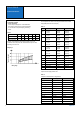
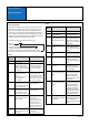
C 16-1 / C 16-3 Technical Information This comparison chart allows a cross reference between American Wire Gauge (AWG) and metric wire sizes (mm 2). Termination methods • Screw connection Screw clamps are designed acc. to EN 60999/VDE 0609. Chart 1 below shows the screw size depending on wire size and the required clamping and testing torque.
C 16-1 / C 16-3 Technical Information • Crimp connection A crimp connection is a non-detachable electrical connection between a wire and a crimp contact produced with the crimp technology. Precise crimping dies which are matched to the crimp barrel and the wire size and a defined deformation result in a reliable electrical connection. There are open crimp barrels (stamped contacts) and closed crimp barrels (turned contacts).
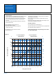
C 16-1 / C 16-3 Technical Information Chart 5 Degree of protection Electrical devices to which connectors belong to have to be protected for safety reasons from outside influences like dust, foreign objects, direct contact, moisture and water. This protection is provided on industrial connectors by its housings with their latching devices and sealed cable entries. The degree of protection can be selected depending on the type of intended use.
C 16-1/16-3 Remarks Safety classification 1. General Remarks These connectors are designed and produced in conformity with the low voltage directive (72/23/EWG) respectively Gerätesicherheitsgesetz and according DIN VDE 57627 (German Law). All technical data refers to mated connectors under live conditions. The safety of the connector system depends on the correct selection of products, proper assembly of the connector device, and a precise fit of the connectors.
C 16-1 Overview 3 + PE Termination screw solder crimp Wire gauge max. 2,5 mm 2; AWG 14 max. 0,75 mm 2; AWG 18 max. 1,5 mm 2; AWG 16 Rated insulation voltage 400 V 250 V 200 V Current carrying capacity 16 A 10 A 13 A Pollution degree 3 3 Installation category III III IP 67 IP 67 Protection class 8 6 + PE No.
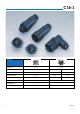
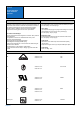
C 16-1 Product description Order information Approvals Product description Order information The circular connectors of the C 16-1 series are designed to meet the high requirements of industrial applications under harsh environmental conditions. The range includes versions with screw, solder and crimp terminations. A selection of crimp contacts for hand crimp tools and crimp machines ensure a reliable termination resulting in qualitative, technical and economical advantages.
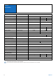
C 16-1 Characteristics General Characteristics Characteristics Standard Number of contacts 3 + PE Electrical Characteristics 6 + PE screw type solder type crimp type 250 V 200 V Rated insulation voltage IEC 60664-1 400 V Rated impulse withstand voltage IEC 60664-1 6000 V 4000 V Pollution degree IEC 60664-1 3 3 Installation (overvoltage) category IEC 60664-1 III III Material group IEC 60664-1 II II Test voltage IEC 60664-1 2450 V 1680 V Current carrying capacity IEC 60512
C 16-1 Derating curves y No of contacts 6 + PE A alle Ansc 24 22 20 18 16 14 12 10 8 6 4 2 Current carrying capacity y g p Current carrying capacity y g p y No of contacts 3 + PE all c wire °C 0 10 20 30 40 50 60 70 80 90100 Ambient temperature Bauelemente Umgebungstemperatur A alle Ko all cont 24 22 20 18 16 14 12 10 8 6 4 2 a) Ansc wire b) Ansc wire a b 0 10 20 30 40 50 60 70 80 90100 110120 B l Ambient t U temperature b t t all contacts wire gauge 2,5 mm2, 14 AWG °C all contacts a) wi
C 16-1 Male cable connectors Description Male cable connector, 3+PE screw, 6+PE solder termination, with strain relief, VDE test certificate of conformity Drawing Part. no. Cable outlet 2) No. of cont.
C 16-1 Female receptacles Panel cutout 2) Description Drawing No. of cont. Part. no. Female receptacle, screw termination, VDE test certificate of conformity 3 + PE T 3111 000 Female receptacle, solder termination, VDE test certificate of conformity 6 + PE T 3107 000 Female receptacle, crimp version, without contacts 1), VDE test certificate of conformity 6 + PE T 3107 500 Please order crimp contacts separatly, see page 30/31, past numbersystem for crimpcontacts see page 32.
C 16-1 Female cable connectors Description Female cable connector, 3+PE screw, 6+PE solder termination, with strain relief, VDE test certificate of conformity Drawing No. of cont. 3 + PE Part No.
C 16-1 Male receptacles Panel cutout 2) Description Drawing No. of cont. Part No.
C 16-1 Accessories Description Protective cap for male cable connector and male receptacle Protective cap for female cable connector and female receptacle Backshell, straight version, packaging unit 10 pcs. Back shell, straight version, with clamping ring, Packaging unit 10 pcs. Figure Part No. for male connector for male receptacle T 6482 001 T 6482 000 for female cable connector for female receptacle T 6483 001 T 6483 000 max. cable diameter 1) PG 9 max.
C 16-3 Shell size 1 No. of contacts 8 + PE 14 + PE 17 + PE Termination crimp crimp crimp Wire gauge mm2 / AWG 0,14 - 2,5 / 26 - 14 0,14 - 2,5 / 26 - 14 0,14 - 1,0 / 26 - 18 Rated insulation voltage 400 V 100 V 100 V Current carrying cap. 12 A 11 x 6 A; 4 x 18 A 6A Pollution degree 3 3 3 Installation category III III III IP 65 IP 65 IP 65 Protection class Shell size 2 No.
C 16-3 Product description Order information Approvals Product description Order information The circular connector series C 16-3 has two housing sizes. The connectors are designed to meet the high requirements of industrial applications under harsh environmental conditions. The range includes versions with screw and crimp terminations. A selection of crimp contacts for hand crimp tools and crimp machines enables a reliable termination resulting in qualitative, technical and economical advantages.
C 16-3 Coding system Polarization Depending on the contact arrangements the polarization of this connector series can be varied. Please take care of the housing and contact insert characteristics. Shell size 1 Shell size 2 No of contacts No of coding possibil. Position No of contacts No of coding possibil.
C 16-3 Characteristics General Characteristics Standard Characteristics Shell size 1 Number of contacts Shell size 2 8 + PE 14 + PE 17 + PE 5 + PE 12 + PE 14 + PE 19 + PE 3 x 500 V 9 x 300 V 3 x 6000 V 9 x 4000 V 400 V 250 V 3110 V 4000 V Electrical Characteristics Rated insulation voltage IEC 60664-1 400 V 100 V 100 V 400 V Rated impulse withstand voltage IEC 60664-1 6000 V 3000 V 3000 V 6000 V Pollution degree IEC 60664-1 3 3 3 3 3 3 3 Installation (overvoltage) cate
C 16-3 Derating curves Shell size 1 8+PE 8+PE a)a)alle all Kcontacts Ø 1,6 Ansch wire gauge 16 AWG all con wire g 15 14 12 10 8 6 4 2 0 10 20 30 40 50 60 70 80 90 100 110 120 Ambient temperature Current carrying capacity A °C 14+PE 14+PE a)a)4 4Kon contacts Ø 2,5 wire gauge 16 AWG Ansch b)4 11 concontacts Ø 1,5 wireg gauge 20 AWG wire b) 11 Ko Ansch 11 con wire g a 20 15 10 b 5 0 10 20 30 40 50 60 70 80 90 100 110 120 Ambient temperature °C 17+PE 17+PE all Kontak contacts Ø 1,5 alle wire ga
C 16-3 View of connector style, Shell size 1 and 2 Identification Male cable connector Figure Description Long version with internal strain relief Conn.
C 16-3 Mounting instruction Torque for back shell min. 1 Nm max.
C 16-3 Shell size 1 Male cable connectors I Description Drawing H K No. of cont. Contacts 2) Part No. Cable outlet 3) PG 11 Male cable connector, long, style I with internal strain relief, without contacts 1) PG 13,5 8 + PE .N 01 016 00... C016 10I008 002 1 C016 10I008 003 1 14 + PE 11 x C016 10I014 002 1 C016 10I014 003 1 .N 01 015 00... 4x .N 01 025 00... 17 + PE .N 01 015 00...
C 16-3 30,2 +0,2 (1.189) 28,6 ±0,1 (1.126) 3,8 +0,1 (.15) Shell size 1 Female receptacles 26,2 +0,2 (1.031) oder M3,5 28,6 ±0,1 (1.126) G Identification SW27,2 +0,2 (1.071) Panel cutout Drawing No. of cont. Female receptacle, without contacts 1) Female receptacle, style N, without contacts 1) N Panel cutout Contacts 2) Part No. 8 + PE .N 02 016 00… C016 10G008 000 1 14 + PE 11 x .N 02 015 00... 4 x .N 02 025 00… C016 10G014 000 1 17 + PE .N 02 015 00...
C 16-3 Shell size 1 Male receptacles C Identification Drawing Male receptacle, style C, without contacts 1) Panel cutout No. of cont. Contacts 2) Part No. 8 + PE .N 01 016 00… C016 10C008 000 1 14 + PE 11 x .N 01 015 00... 4x .N 01 025 00… C016 10C014 000 1 17 + PE .N 01 015 00... C016 10C017 000 1 C 16-3 Shell size 1 Accessories Identification Drawing Protective cap for male cable connector and male receptacle. Part No.
C 16-3 Shell size 2 Male cable connectors I Description Drawing H K No. of cont.
C 16-3 Shell size 2 Female cable connectors E Description D Drawing F No. of cont. Contacts 2) Part No. Cable outlet 3) PG 16 PG 13,5 Female cable connector, long, style E with internal strain relief, 5 + PE screw termination, 12 + PE-, 14 + PE and 19 + PEversion without contacts 1) 5 + PE – Female cable connector, style F with clamping ring, 5 + PE screw termination, 12 + PE-, 14 + PE and 19 + PEversion without contacts 1) C016 20E005 103 2 C016 20E005 104 2 C016 20E005 105 2 12 + PE 9 x .
C 16-3 Shell size 2 Accessories Description Protective cap for male cable connector and male receptacle Protective cap for female cable connector and female receptacle Disassembly tool for pin-and socket inserts Amphenol Figure Part No.
C 16-1 und 16-3 Crimp contacts Pin Series C 16-1 C 16-1 C 16-3 C 16-3 C 16-3 C 16-3 C 16-3 C 16-3 Contact Ø in mm 1,6 1,6 1,5 1,5 1,6 1,6 1,6 2,5 Insulation No. of cont.
C 16-1 und 16-3 Crimp contacts Socket Series C 16-3 C 16-3 C 16-1 Contact Ø in mm 1,5 1,5 1,6 Insulation No. of cont. Ø in mm 1,0 - 2,0 1,6 - 2,3 1,0 - 2,0 C 16-3 C 16-1 1,6 1,8 - 2,8 C 16-3 C 16-1 1,6 2,5 - 3,5 C 16-3 C 16-3 C 16-3 Amphenol 2,5 2,5 1,8 - 2,8 2,5 - 3,5 Shell size Wire gauge in mm2 AWG Supplied as pcs. Part No.
Part No. system for crimp contacts VN __ 1) 1) supplied as: 01 _ 016 _ 0001 _ (1) _ 2) 3) 4) 5) VN = single contact 100 pcs. ZN = contacts on reel 100, 200 or 400 contacts HN = Contacts on reel with 2000 contacts for Acrimat FD (contact feeding right hand side) TN = Contacts on reel with 2000 contacts for Acrimat II + III (contact feeding left hand side) 2) Type of contact: 01 = male contact 02 = emale contacts 3) Contact pin dia.: e. g.
Summary of Part No. Part No. Page Part No. Page Part No. Page Part No.
Summary of Part No. 34 Part No. Page Part No. Page Part No. Page Part No.