
Instruction manual

AMPDIO DRIVERS
Page 73
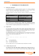
BIT ASSIGNMENTS
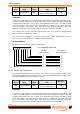
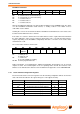
The bit layout of the counter 2 register is shown below.
7 6 5 4 3 2 1 0
First Byte
(Least Significant)
8
9
10
11
12
13
14
15
Second Byte
(Most Significant)
0
1
2
3
4
5
6
7
16 BIT COUNTER 2 DATA BIT
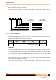
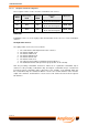
5.4.2.4 Counter/Timer Control Register
The control register provides the means to configure the three sixteen bit counter/timers of the
82C54. An outline of its operation is given here, but reference should be made to the 82C54 device
manufacturers’ data sheets in the appendices on the SOFTMAN CD before programming of the
counter is attempted.
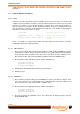
The Counter Timer Control register is a WRITE register.
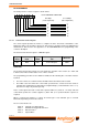
Register
Offset
Write and/or
Read
Register
Width
Register
Title
Mnemonic
03
16
Write 8 bits
82C54 Counter/Timer
Control Register
CTC
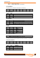
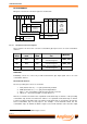
FUNCTION
The Counter Timer Control register is used to define the operation of the counters 0, 1 and 2, and
to latch counter values and/or status of one or more counters.
The programming procedure for the 82C54 is flexible, but the following two conventions must be
followed:
For each counter, the control word must be written before the initial count is loaded.
The initial count must follow the count format specified in the control word. This format is
normally least significant byte followed by most significant byte (control word bits 5 & 4 = 1 & 1)
but can be L.S. byte only or M.S. byte only.
As the control register and each counter have separate addresses (offsets 0, 1, 2 and 3) and each
control word specifies the counter it applies to (bits 6 and 7) no special instruction sequence is
required.
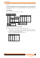
When a control word is written to a counter, all control logic is reset and OUT goes to a known
initial state depending on the mode selected.
The six counter modes are:
Mode 0 Interrupt on Terminal Count
Mode 1 Hardware Re-triggerable One-shot
Mode 2 Rate Generator
Mode 3 Square Wave