
User guide

2 3
NEED HELP?
CALL 800-267-5486
OR 847-498-9000
EMAIL:
CUSTOMERSERVICE@
AMPLI.COM
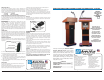
NO TOOL ASSEMBLY OF LECTERN
SPEAKER COVER / AMPLIFIER
8. Remove and unpack the speaker cover.
9. Attach the speaker cover to the front of
the shroud by pushing the plastic posts in
each corner of the cover into the rubber
receptacles in the front of the shroud. See
figure 4 and 5.
Please read all instructions first and then follow the steps below:
BASE ASSEMBLY
1. Remove center column and shroud assembly from the shipping
carton and place as shipped (face down) on the floor or on a suitable
sturdy table.
2. Remove and unpack the base from the shipping carton.
3. Assemble the base to the column as shown in FIGURE 1 by using four
of the 2 inch long neural knob screws supplied with the lectern.
TIP: Do not completely tighten each screw as you place it through the
base and into the column. Wait until all four screws have been put into
the proper position and then tighten them up.
4. Turn the base and column assembly upright. If assembled on a table
place the unit upright on the floor.
READING TABLE ASSEMBLY
5. Remove and unpack the lectern reading table.
6. Attach the table to the top of the column. See FIGURE 2. This is
accomplished by placing the table top on the column base and lining
up the corners.
TIP: the corners need to be lined up in order to get the screws in the
table top.
7. Fasten the reading table to the colum with the 4 1 inch long neural
knob screws supplied. The knob screw goes up into the reading table
throught the 4 holes in the column (see FIGURE 2).
FIGURE 1
FRONT VIEW
FIGURE 2
BASE
CENTER
COLUMN
READING
TABLE
CENTER
COLUMN
INSTALL NEURAL
KNOBS FROM
BASE INTO
COLUMN
THE CORNERS NEED TO
BE LINED UP IN ORDER
TO GET THE SCREWS IN
THE TABLE TOP.
10. Flush mount ampifier is built-in.
11. For an optional speaker installation (S1201) make sure the speaker
connection cable is routed through the proper notch in the back face of
the amplifier pocket of the shroud so that the table will not pinch the
cable when mounted. See FIGURE 3 .
12. (SW505A) Make sure the antenna cable is also routed through the
notch in the same manner.
13. SW505A ONLY - Insert the small (2.5mm) plug into the amplifier
jack labeled ‘Antenna.’
14. See the amplifier operation manual for further instructions regarding
operation of the sound system.
OPERATION OF ADJUSTABLE LECTERN
This lectern adjusts from 39 inches to 45 inches measured from the
Amplifier side. To adjust the lectern height:
1. With one hand flat in the center of the table holding it down loosen
the adjustable height knob with the other hand.
2. You may extend the lectern up to its maximum height of 45 inches.
3. To lower the lectern, lightly press down on the reading table until the
desired height is reached and retighten the height-locking knob.
TIP: The knob locks at any height by tightening it. The lectern will adjust
from 45 inches down to 39 inches when measured from the amplifier
side.
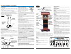
ASSEMBLY OF FLEXIBLE GOOSENECK: (FIGURE 3)
To install the 1. GOOSENECK onto the 2. MOUNTING FLANGE located
by the far left corner of the desktop reading surface, first turn the neck
piece clockwise onto the mount. Next install the microphone holder (U
shaped piece) onto the end of the gooseneck by turning it clockwise
onto the top of the neck. You can then slide the 3. MICROPHONE into
the 4. MICROPHONE HOLDER as shown.
The 5. MIC CORD has a plug with three small holes in one end, A for
connecting with the microphone, and a ¼ in. male plug on the other
end, B for connecting with the unit on the control panel. Connect the
end with the three holes to the base of the microphone, and plug the
male ¼ in. end of the microphone cord into the jack labeled DYNAMIC.
The microphone has an ON/OFF switch. it should always be in the OFF
position until the main power is ON and you are ready to speak.
TO INSTALL OR REPLACE BATTERIES
Remove all cables and plugs from amplifier. Unscrew the thumb screws.
Pull carriage out to install new batteries, Insert 10 new Alkaline “D”
cell batteries, be sure to observe polarity, or replace with S1465 NiCad
battery pack. Carefully replace battery carriage. Reattach battery
door.
TIP:
Do not mix battery types or attempt to recharge alkaline batteries
- equipment damage, safety hazard or fire could result.
OPTIONAL POWER SUPPLY INSTALLATION
Optional Power Supplies may be substituted. Model S1460, International
AC Adapter/Recharger (110/220V, 50/60Hz). Model S1462, 12 Volt
DC adapter (automotive cigarette lighter plug-in). S1465 NiCad Battery
Pack.
5. MIC
CORD B
1. FLEXIBLE
GOOSENECK
4. SHOCKMOUNT MIC
HOLDER
2. MOUNTING
FLANGE
3. MICROPHONE
5. MIC CORD A
BASE
CENTER
COLUMN
READING
TABLE
TO OPERATE:
Plug microphone into DYNAMIC Microphone jack.
Plug straight end of 12” speaker cable into built in speaker jack and
right angle end into left SPEAKER jack on amplifier.
Turn Amplifier on (switch is located on the front of the amplifier). The
red light will go on, showing that power is available. Rotate VOLUME
control knob to obtain desired loudness level throughout the coverage
area.
MICROPHONE VOLUME
Controls the volume level of the microphones, including the wireless
microphones.
MICROPHONE INPUTS
There are three microphone inputs, which can be used
simultaneously:
DYNAMIC - for standard dynamic microphones 1/4 in.
CONDENSER - for electret or condenser microphones, which require
phantom power (supplied from the amplifier) 3.5mm
WIRELESS - accepts output from an external wireless microphone
receiver
AUXILIARY
The LINE IN provision is for connecting an external audio source such
as a CD player, tape player, MP3 player or computer sound card This
input also serves as a provision for connecting additional wireless
microphone receivers, audio mixers and other line level audio
sources.
Separate VOLUME and TONE control knobs allow flexibility in
controlling the sound quality as well as balancing the auxiliary source
with the microphones.
OUTPUT
The LINE OUT provision may be used for connecting to an input on
a recording device, such as a computer sound card, MP3 recorder,
tape recorder, or similar device. The LINE OUT can also be used
for a number of other applications, such as connecting to a house
system, or connecting to one of our wireless speaker transmitters,
for example.
INTERNAL SPEAKERS
The internal speakers are wired for stereo, LEFT and RIGHT channel
information is reproduced by the appropriate speaker inside the
unit.
EXTERNAL SPEAKERS
Two separately amplified speaker jacks allow you to use one or two
S1201, S1290, or any of our horn speakers for additional sound
power. Note: when using a stereo AUX source with a single speaker,
only one of the stereo channels will be heard. However, all MIC inputs
are heard equally on both channels.
IINTERNAL WIRELESS MICROPHONE RECEIVER *SW Model only*
Power ‘ON’ and ‘OFF’; Frequency ‘A’ and ‘B’ switches. Frequency
should match wireless transmitter. The red light above these switches
will come on when the wireless microphone receiver is active.
TONE
L - SPEAKER - R
VOLUME
DYNAMIC
VOLUME
1
WRLS 1
ON
LINE IN
WIRELESS
CONDENSER
LINE OUT
ON
OFF
A
B
EXTEND YOUR VOICE WITH
1-800-267-5486
WWW.AMPLI.COM
MADE IN USA
ON
ON
OFF
AUX OUT
DC IN
MAIN
32
POWER MICROPHONES
AUXILIARY OUTPUT
MAIN
POWER
SWITCH
INTERNAL
WIRELESS MIC
RECEIVERS
MASTER
VOLUME
MIC
INPUT
MIC
INPUT
MIC
INPUT
LINE IN
JACK
LINE OUT
JACK
SPEAKER
JACKS
TONE
CONTROL
AUXILIARY
VOLUME
POWER
INPUT
AUX
OUT
ON-OFF
When switch is in the ON position, the red light
will be on.
DC IN
Connection for optional adapter:
S1460 Universal AC Adapter (110/220V,
50/60Hz)
S1465 Nicad Battery Pack (requires S1460 AC
Adapter/recharger)
AUX OUT
Power source for 12 to 15V DC accessories.
S505A & SW505A CONTROL PANEL
AMPLIFIER
ADJUSTABLE
HEIGHT DIAL
USE TO ADJUST
LECTERN
HEIGHT FROM
39 TO 45 INCHES
STORAGE
SPAGE FOR
OPTIONAL
S1201
SPEAKERS
FIGURE 3
BATTERY PANEL
TO INSTALL
OR CHANGE
BATTERIES,
REMOVE THUMB
SCREWS AND
PULL OUT
CARRIAGE.