
Laptop User Manual

Chapter 3 Hardware
26 Reference Manual MightyBoard 821
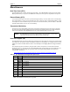
Ethernet External LED
This header is for an external LED for Ethernet power and activity.
Note: The shaded area denotes power or ground.
Serial Console
The MightyBoard 821 supports the serial console (or console redirection) feature. This I/O function is
provided by an ANSI-compatible serial terminal, or the equivalent terminal emulation software running on
another system. This can be very useful when setting up the BIOS on a production line for systems that are
not connected to a keyboard and display.
Infrared (IrDA) Port
The Infrared Data Association (IrDA) port provides a two-way wireless communications port using infrared
as a transmission medium at the basic level. There are two basic infrared implementations provided; the
Hewlett-Packard Serial Infrared (HPSIR) and the Amplitude Shift Keyed Infrared (ASKIR) methods.
HPSIR is a serial implementation of infrared developed by Hewlett-Packard. The control of the IrDA port
(HPSIR and ASKIR) is Operating System specific and not configured in the BIOS Setup Utility. Typically,
the IrDA port shares the same control signals and IRQ settings with Serial Port 2.
The HPSIR method allows serial communication at baud rates up to 115k baud. Each word is sent serially
beginning with a zero value start bit. A zero is sent when a single infrared pulse is sent at the beginning of
the serial bit time. A one is sent when no infrared pulse is sent during the bit time.
The Amplitude Shift Keyed infrared (ASKIR) allows serial communication at baud rates up to 19.2k baud.
Each word is sent serially beginning with a zero value start bit. A zero is sent when a 500kHz waveform is
sent for the duration of the serial bit time. A one is sent when no transmission is sent during the serial bit
time.
Both of these methods require an understanding of the timing diagrams provided in the Super I/O controller
(W83627HF) specifications available from the manufacture’s web site and referred to earlier in this manual.
For more information, refer to the W83627HF chip databook and the Infrared Data Association web site at
http://www.irda.org
.
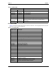
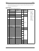
Table 3-10. Ethernet External LED Pin/Signal Descriptions (JP6)
Pin # Signal Description
1 ACT#1 Ethernet Activity 1
2 ACT#2 Ethernet Activity 2
3 LINK#1 Ethernet Link 1
4 LINK#2 Ethernet Link 2
5
VCC3 +3 volts – Provides +3 volts to external LED
6 LEDP2 LED positive 2
7 SPEED1 LED speed 1
8 SPEED2 LED speed 2
NOTE For faster speeds and infrared applications not covered in this brief description, refer
to the W83627HF chip specifications by Nuvoton.
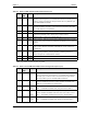
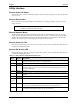
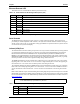
Table 3-11. Infrared (IrDA) Interface Pin/Signal Descriptions (J7)
Pin # Signal Description
1
VCC +5 volts
2IRTX IR Transmit Data
3 CIRRX IR Mode Select