COM 830 (Computer-On-Module) Reference Manual P/N 5001829A Revision A
Notice Page NOTICE No part of this document may be reproduced, transmitted, transcribed, stored in a retrieval system, or translated into any language or computer language, in any form or by any means, electronic, mechanical, magnetic, optical, chemical, manual, or otherwise, without the prior written permission of Ampro Computers, Incorporated.
Contents Chapter 1 About This Manual ....................................................................................................1 Symbols ...........................................................................................................................................1 Warning .................................................................................................................................1 Caution .............................................................................
Contents Secondary Connector Rows C and D ...................................................................................... 15 PCI Express Graphics (PEG) ................................................................................................... 15 SDVO ....................................................................................................................................... 15 PCI Bus .................................................................................................
Contents Chapter 4 BIOS Setup Description..........................................................................................53 Entering the BIOS Setup Program.................................................................................................53 Boot Selection Popup ...............................................................................................................53 Manufacturer Default Settings .................................................................................
Contents List of Tables Table 1-1. Table 1-2. Table 1-3. Table 2-1. Table 2-2. Table 2-3. Table 2-4. Table 3-1. Table 3-2. Table 3-3. Table 3-4. Table 3-5. Table 3-6. Table 3-7. Table 3-8. Table 3-9. Table 3-10. Table 3-11. Table 3-12. Table 3-13. Table 3-14. Table 3-15. Table 3-16. Table 3-17. Table 3-18. Table 3-19. Table 3-20. Table 3-21. Table 3-22. Table 3-23. Table 3-24. Table 3-25. Table 3-26. Table 3-27. Table 3-28. Table 3-29. Table 3-30. Table 3-31. Table 3-32. Table A-1.
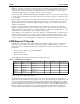
Chapter 1 About This Manual This manual provides information about the components, features, connectors and BIOS Setup menus available on the COM 830. Symbols The following symbols are used in this manual: Warning Warnings indicate conditions that, if not observed, can cause personal injury. Caution Cautions warn the user about how to prevent damage to hardware or loss of data. Note Notes call attention to important information that should be observed. Terminology Table 1-1.
Chapter 1 About This Manual Beginning on the date of shipment to its direct customer and continuing for the published warranty period, Ampro represents that the products are new and warrants that each product failing to function properly under normal use, due to a defect in materials or workmanship or due to non conformance to the agreed upon specifications, will be repaired or exchanged, at Ampro's option and expense.
Chapter 1 About This Manual Carrier board designers can utilize as little or as many of the I/O interfaces as necessary. The carrier board can therefore provide all the interface connectors required to attach the system to the application specific peripherals. This versatility allows the designer to create a dense and optimized package, which results in a more reliable product while simplifying system integration.
Chapter 1 4 About This Manual Reference Manual COM 830
Chapter 2 Specifications Feature List Table 2-1. Feature Summary Form Factor Based on COM Express™ standard pinout Type 2 (Basic size 95 x 125mm) Processor Intel® Core™ Duo U2500 ULV 1.2GHz, with 2-MByte L2 cache ULV (Ultra Low Voltage) Intel® Celeron M 423 ULV 1.07GHz, with 1-MByte L2 cache (Ultra Low Voltage) Memory 2 sockets: SO-DIMM DDR2 667 up to 4-GByte physical memory. Sockets located top and bottom side of module.
Chapter 2 Specifications Table 2-1. Feature Summary (Continued) BIOS Based on AMIBIOS8® -1MByte Flash BIOS with Embedded BIOS features. Power Management ACPI 2.0 compliant with battery support. Also supports Suspend to RAM (S3). NOTE Some of the features mentioned in the above Feature Summary are optional.
Chapter 2 Specifications Electrostatic Sensitive Device All COM 830 variants are electrostatic sensitive devices. Do not handle the COM 830, or processor, except at an electrostatic-free workstation. Failure to do so may cause damage to the module and/or processor and void the manufacturer’s warranty. Supply Voltage Standard Power 12V DC ± 5% Electrical Characteristics Power supply pins on the module's connectors limit the amount of input power.
Chapter 2 Specifications Windows XP Professional Standby Mode (requires setup node “Suspend Mode” in the BIOS to be configured to S1 POS [Power On Suspend]) Suspend to RAM (requires setup node “Suspend Mode” in BIOS to be configured to S3 STR [suspend to RAM]) NOTE The PassMark, Burn-In Test-Suite was used to stress the CPU to 100% workload. Processor Information In the following power tables there is some additional information about the processors.
Chapter 2 Specifications Table 2-4. COM 830 Intel® Celeron M 423 1.07GHz 1MB L2 cache COM 830-R-10 Intel® Celeron M 423 1.06GHz 1MB L2 cache ULV 65nm Memory Size 512MB Operating System Windows XP Professional SP2 Power State Desktop Idle 100% workload Standby (S1) Suspend to Ram (S3) Power consumption (measured in Amperes/Watts) 1.26A/15.10W 1.90A/22.82W 1.60A/19.23W 0.82A/9.
Chapter 2 Specifications Block Diagram Composite Video Component Video OR TV-Out System Bus (533 or 667MHz) S-Video PCI Express Graphics x16 GMCH CRT x16 Intel 82945GM LCD I/F (LVDS) OR 2x SDVO DDR2-SODIMM Socket (top) DMI Interface SM Bus Memory Bus (533 or 667MHz) DDR2-SODIMM Socket (bottom) AC’97 Digital Audio / HDA Interface PCI Bus 1x IDE (Primary) 2x SATA [ [ 3&,H A-B 8x USB 2.
Chapter 2 Specifications Heatspreader An important factor for each system integration is the thermal design. The heatspreader acts as a thermal coupling device to the module. It is a 3mm thick aluminum plate. The heatspreader is thermally coupled to the CPU via a thermal gap filler and on some modules it may also be thermally coupled to other heat generating components with the use of additional thermal gap fillers.
Chapter 2 Specifications Heatspreader Dimensions Heatspreader is available for all variants of COM 830. NOTE 12 All measurements are in millimeters. Torque specification for heatspreader screws is 0.5 Nm.
Chapter 2 Specifications Connector Subsystems Rows A, B, C, D The COM 830 is connected to the carrier board via two 220-pin connectors (COM Express Type 2 pinout) for a total of 440 pins connectivity. These connectors are broken down into four rows. The primary connector consists of rows A and B while the secondary connector consists of rows C and D. In this view the connectors are seen “through” the module.
Chapter 2 Specifications PCI Express™ The COM 830 offers 6x x1 PCI Express lanes via the Intel 82801GHM (ICH7M-DH), which can be configured to support PCI Express edge cards or ExpressCards. One of the six x1 PCI Express lane is utilized by the onboard Ethernet controller therefore there are only 5x x1 PCI Express lanes available on the A,B connector row. The PCI Express interface is based on the PCI Express Specification 1.0a.
Chapter 2 Specifications Power Supply Implementation Guidelines 12 volt input power is the sole operational power source for the COM 830. The remaining necessary voltages are internally generated on the module using onboard voltage regulators.
Chapter 2 Specifications Onboard Microcontroller The COM 830 is equipped with an ATMEL Atmega168 microcontroller. This onboard microcontroller plays an important role for most of the BIOS features. It fully isolates some of the embedded features such as system monitoring or the I²C bus from the x86 core architecture, which results in higher embedded feature performance and more reliability, even when the x86 processor is in a low power mode.
Chapter 2 Specifications Simplified Overview of BIOS Setup Data Backup , Ampro Ampro The above diagram provides an overview of how the BIOS Setup Data is backed up on modules. OEM default values mentioned above refer to customer specific CMOS settings created using the System Utility tool. Once the BIOS Setup Program has been entered and the settings have been changed, the user saves the settings and exits the BIOS Setup Program using the F10 key feature.
Chapter 2 Specifications Security Features The COM 830 can be equipped optionally with a “Trusted Platform Module” (TPM 1.2). This TPM 1.2 includes co-processors to calculate efficient hash and RSA algorithms with key lengths up to 2,048 bits as well as a real random number generator. Security sensitive applications like gaming and e-commerce will benefit also with improved authentication, integrity and confidence levels. Suspend to Ram The Suspend to RAM feature is available on the COM 830.
Chapter 2 Specifications Native vs. Compatible IDE mode Compatible Mode When operating in compatible mode, the SATA and PATA (Parallel ATA) controller together need two legacy IRQs (14 and 15) and are unable to share these IRQs with other devices. This is a result of the fact that the SATA and PATA controller emulate legacy IDE controllers.
Chapter 2 Specifications any damage to the processor as a result of overheating. The THERMTRIP# signal activation is completely independent from processor activity and therefore does not produce any bus cycles. NOTE In order for THERMTRIP# to be able to automatically switch off the system it is necessary to use an ATX style power supply.
Chapter 2 3. Specifications 64-bit Mode: 64-bit operating system and 64-bit applications. This usage requires 64-bit device drivers. It also requires applications to be modified for 64-bit operation and then recompiled and validated. Intel 64 provides support for: 64-bit flat virtual address space 64-bit pointers 64-bit wide general purpose registers 64-bit integer support Up to one Terabyte (TB) of platform address space You can find more information about Intel 64 Technology at: http://developer.
Chapter 2 Specifications Active Cooling During this cooling policy the operating system is turning the fan on/off. Although active cooling devices consume power and produce noise, they also have the ability to cool the thermal zone without having to reduce the overall system performance. Use the “active cooling trip point” setup node in the BIOS setup program to determine the temperature threshold that the operating system will use to start the active cooling device.
Chapter 2 Specifications GPI2# Set GPE2 Function node to Sleep Button in the ACPI setup menu or set Resume On Ring to Enabled in the Power setup menu. Onboard LAN Event Device driver must be configured for Wake On LAN support. SMBALERT# Wakes unconditionally from S1-S5. PCI Express WAKE# Wakes unconditionally from S1-S3.
Chapter 2 Specifications USB 2.0 EHCI Host Controller Support The 8 USB ports are shared between an EHCI host controller and the 4 UHCI host controllers. Within the EHC functionality there is a port-routing logic that executes the mixing between the two different types of host controllers (EHCI and UHCI). This means that when a USB device is connected the routing logic determines who owns the port. If the device is not USB 2.
Chapter 3 Signals and Pinout Tables The following section describes the signals found on COM Express™ Type II connectors used for Ampro modules. The table below describes the terminology used in this section for the Signal Description tables. The PU/PD column indicates if a COM Express internal pull-up or pull-down resistor has been used. If the field entry area in this column for the signal is empty, then no pull-up or pull-down resistor has been implemented.
Chapter 3 Signals and Pinout Tables A-B Connector Signal Descriptions Table 3-2. AC'97/Intel® High Definition Audio Link Signals Descriptions Signal Description I/O AC_RST# AC ’97/Intel High Definition Audio Reset: This signal is the master hardware reset to external codec(s). O 3.3V AC_SYN C AC ’97/Intel High Definition Audio Sync: This signal is a 48 kHz fixed rate sample sync to the codec(s). It is also used to encode the stream number. O 3.
Chapter 3 Signals and Pinout Tables AC_SYNC and AC_SDOUT can be used to switch PCI Express channels 1-4 between x1 and x4 mode. If both signals are each pulled-up (using 1k resistors) to 3.3V at the rising edge of PWROK then x4 mode is enabled. x1 mode is used by default if these resistors are not populated. Table 3-3. Gigabit Ethernet Signal Descriptions Gigabit Ethernet Description I/O GBE0_MDI[0:3]+ Gigabit Ethernet Controller 0: Media Dependent Interface Differential Pairs 0, 1, 2, 3.
Chapter 3 Signals and Pinout Tables Table 3-4. Serial ATA Signal Descriptions (Continued) SATA2_RX+ SATA2_RX- Serial ATA channel 2, Receive Input differential pair. I SATA Not supported SATA2_TX+ SATA2_TX- Serial ATA channel 2, Transmit Output differential pair. O SATA Not supported SATA3_RX+ SATA3_RX- Serial ATA channel 3, Receive Input differential pair. I SATA Not supported SATA3_TX+ SATA3_TX- Serial ATA channel 3, Transmit Output differential pair.
Chapter 3 Signals and Pinout Tables Table 3-5. PCI Express Signal Descriptions [general purpose] (Continued) PCIE3_TX+ PCIE3_TX- PCI Express channel 4, Transmit Output differential pair O PCIE Supports PCI Express Base Specification, Revision 1.0a PCIE4_RX+ PCIE4_RX- PCI Express channel 5, Receive Input differential pair I PCIE Supports PCI Express Base Specification, Revision 1.
Chapter 3 Signals and Pinout Tables Table 3-8. USB Signal Descriptions 30 Signal Description I/O USB0+ USB Port 0, data + or D+ I/O USB 2.0 compliant and backwards compatible to USB 1.1 USB0- USB Port 0, data - or D- I/O USB 2.0 compliant and backwards compatible to USB 1.1 USB1+ USB Port 1, data + or D+ I/O USB 2.0 compliant and backwards compatible to USB 1.1 USB1- USB Port 1, data - or D- I/O USB 2.0 compliant and backwards compatible to USB 1.
Chapter 3 Signals and Pinout Tables Table 3-8. USB Signal Descriptions (Continued) USB7- USB Port 7, data - or D- I/O USB 2.0 compliant and backwards compatible to USB 1.1 USB_0_1_OC# USB over-current sense, USB ports 0 and 1. A pullup for this line shall be present on the module. An open drain driver from a USB current monitor on the carrier board may drive this line low. Do not pull this line high on the carrier board. I 3.3VSB PU 10k 3.
Chapter 3 Signals and Pinout Tables Table 3-9. CRT Signal Descriptions (Continued) VGA_BLU Blue for monitor. Analog DAC output, designed to drive a 37.5-Ohm equivalent load. O PD 150R VGA_HSYN C Horizontal sync output to VGA monitor O 3.3V VGA_VSYN C Vertical sync output to VGA monitor O 3.3V VGA_I2C_C K DDC clock line (I²C port dedicated to identify VGA monitor capabilities) I/O 5V PU 2k2 5V VGA_I2C_D AT DDC data line. I/O 5V PU 2k2 5V Analog output Analog Table 3-10.
Chapter 3 Signals and Pinout Tables Table 3-11. TV-Out Signal Descriptions (Continued) TV_DAC_B TVDAC Channel B Output supports the following: Composite video: not used Component video: Luminance (Y) analog signal. O PD 150R Analog output PD 150R Analog output Comment Analog S-Video: Luminance analog signal. TV_DAC_C TVDAC Channel C Output supports the following: Composite video: not used Component: Chrominance (Pr) analog signal. O Analog S-Video: Chrominance analog signal. Table 3-12.
Chapter 3 Signals and Pinout Tables Table 3-13. General Purpose I/O Signal Descriptions Signal Description I/O PU/PD GPO[0] General purpose output pins. Upon a hardware reset, these outputs should be low. O 3.3VSB PU 10k 3.3VSB GPO[1] General purpose output pins. Upon a hardware reset, these outputs should be low. O 3.3VSB PU 10k 3.3VSB GPO[2] General purpose output pins. Upon a hardware reset, these outputs should be low. O 3.3VSB PU 10k 3.3VSB GPO[3] General purpose output pins.
Chapter 3 Signals and Pinout Tables Table 3-14. Power and System Management Signal Descriptions (Continued) SUS_S3# Indicates system is in Suspend to RAM state. Active low output. Also known as "PS_ON" and can be used to control an ATX power supply. O 3.3VSB PU 10k 3.3VSB SUS_S4# Indicates system is in Suspend to Disk state. Active low output. O 3.3VSB PU 10k 3.3VSB SUS_S5# Indicates system is in Soft Off state. O 3.3VSB PU 10k 3.3VSB WAKE0# PCI Express wake up signal. I 3.3VSB PU 10k 3.
Chapter 3 Signals and Pinout Tables Table 3-15. Power and GND Signal Descriptions VCC_RTC Real-time clock circuit-power input. Nominally +3.0V. P GND Ground - DC power and signal and AC signal return path. P All available GND connector pins shall be used and tied to Carrier Board GND plane. A-B Connector Pinout Table 3-16.
Chapter 3 Signals and Pinout Tables Table 3-16.
Chapter 3 Signals and Pinout Tables Table 3-16.
Chapter 3 Signals and Pinout Tables Table 3-17. PCI Signal Descriptions (Continued) PCI_TRDY# PCI bus Target Ready control line, active low I/O 3.3V PU 8k2 3.3V PCI_STOP# PCI bus STOP control line, active low, driven by cycle initiator I/O 3.3V PU 8k2 3.3V PCI_PAR PCI bus parity I/O 3.3V PCI_PERR# Parity Error: An external PCI device drives PERR# when it receives data that has a parity error. I/O 3.3V PU 8k2 3.3V PCI_REQ[0:3]# PCI bus master request input lines, active low. I 3.
Chapter 3 Signals and Pinout Tables Table 3-18. IDE Signal Descriptions (Continued) IDE_IOR# I/O read line to IDE device. O 3.3V IDE_REQ IDE Device DMA Request. It is asserted by the IDE device to request a data transfer. I 3.3V IDE_ACK# IDE Device DMA Acknowledge. O 3.3V IDE_CS1# IDE Device Chip Select for 1F0h to 1FFh range. O 3.3V IDE_CS3# IDE Device Chip Select for 3F0h to 3FFh range. O 3.3V IDE_IORDY IDE device I/O ready input. Pulled low by the IDE device to extend the cycle. I 3.
Chapter 3 Signals and Pinout Tables Table 3-20.
Chapter 3 Signals and Pinout Tables NOTE Some signals have special functionality during the reset process. They may bootstrap some basic important functions of the module. Table 3-21. Module Type Definition Signal Description Signal Description I/O Comment TYPE[ 0:2]# The TYPE pins indicate to the Carrier Board the Pin-out Type that is implemented on the module. The pins are tied on the module to either ground (GND) or are no-connects (NC). For Pinout Type 1, these pins are don’t care (X).
Chapter 3 Signals and Pinout Tables C-D Connector Pinout Table 3-23.
Chapter 3 Signals and Pinout Tables Table 3-23.
Chapter 3 Signals and Pinout Tables Boot Strap Signals Table 3-24. Boot Strap Signal Descriptions Signal Description of Boot Strap Signal I/O AC_SYNC AC ’97/Intel® High Definition Audio Sync: This signal is a 48 kHz fixed rate sample sync to the codec(s). It is also used to encode the stream number. O 3.3V AC_SYNC is a boot strap signal (see caution statement below) AC_SDOUT AC ’97/Intel High Definition Audio Serial Data Out: This signal is the serial TDM data output to the codec(s).
Chapter 3 Signals and Pinout Tables CAUTION The signals listed in the table above are used as chipset configuration straps during system reset. In this condition (during reset), they are inputs that are pulled to the correct state by either COM Express internally implemented resistors or chipset internally implemented resistors that are located on the module.
Chapter 3 Signals and Pinout Tables Table 3-26.
Chapter 3 Signals and Pinout Tables Interrupt Request (IRQ) Lines Table 3-27.
Chapter 3 Signals and Pinout Tables Table 3-28.
Chapter 3 Signals and Pinout Tables Table 3-29. PCI Configuration Space Map (Continued) 50 00h 02h 01h N.A.
Chapter 3 Signals and Pinout Tables Table 3-29.
Chapter 3 Signals and Pinout Tables Table 3-31. PCI Interrupt Routing Map (continued) PIRQ Table 3-32.
Chapter 4 BIOS Setup Description The following section describes the BIOS setup program. The BIOS setup program can be used to view and change the BIOS settings for the module. Only experienced users should change the default BIOS settings. Entering the BIOS Setup Program. The BIOS setup program can be accessed by pressing the key during POST. Boot Selection Popup The BIOS offers the possibility to access a Boot Selection Popup menu by pressing the key during POST.
Chapter 4 BIOS Setup Description Tab Select setup fields (e.g. in date and time). F1 Display General Help screen. F2/F3 Change Colors of setup screen. F7 Discard Changes. F9 Load optimal default settings. F10 Save changes and exit setup. ESC Discard changes and exit setup. ENTER Display options of a particular setup item or enter submenu. Main Setup Screen When you first enter the BIOS setup, you will enter the Main setup screen.
Chapter 4 BIOS Setup Description Advanced Setup Select the Advanced tab from the setup menu to enter the Advanced BIOS Setup screen.
Chapter 4 BIOS Setup Description ACPI Configuration Submenu Feature Options Description ACPI Aware O/S No Yes Set this value to allow the system to utilize the Intel ACPI (Advanced Configuration and Power Interface). Set to NO for non ACPI aware operating system like DOS and Windows NT. Set to YES if your OS complies with the ACPI specification (e.g. Windows XP) ACPI Version Features ACPI v1.0 ACPI version supported by the BIOS ACPI code and tables. ACPI v2.0 ACPI v3.
Chapter 4 BIOS Setup Description NOTE In ACPI mode it is not possible for a “Watchdog ACPI Event” handler to directly restart or shutdown the OS. For this reason the BIOS will do one of the following: For Shutdown: An over temperature notification is executed. This causes the OS to shut down in an orderly fashion. For Restart: An ACPI fatal error is reported to the OS. It depends on your particular OS as to how this reported fatal error will be handled when the Restart function is selected.
Chapter 4 BIOS Setup Description PCI IRQ Resource Exclusion Submenu Feature Options Description IRQ xx Available Reserved Allow or restrict the BIOS from giving IRQ resource to PCI/PNP devices. PCI Interrupt Routing Submenu Feature Options Description PIRQ xx (devices) Auto, 3, 4, .., 14, 15 Select fixed IRQ for PCI interrupt line or set to AUTO to let the BIOS and operating system route an IRQ. Note: Make sure that the selected IRQ is not assigned to legacy I/O.
Chapter 4 DVMT/FIXED Memory BIOS Setup Description 64MB Amount of DRAM the DVMT graphics driver can or will allocate (depends on DVMT mode selected). 128MB Maximum DVMT Boot Display Device Auto Select the display device(s) used for boot up. CRT only LFP = Local Flat Panel (LVDS) SDVO only CRT + SDVO LFP only Note: Auto feature only works with a DDC compatible CRT monitor.
Chapter 4 SDVO Port B Device BIOS Setup Description None Select the SDVO device connected to this port. DVI TV CRT LVDS SDVO Port C Device None Select the SDVO device connected to this port. DVI TV CRT LVDS TV Standard VBIOS-Default NTSC PAL Select TV standard that should be supported. TV connection type is automatically detected by the Video BIOS. SECAM SMPTE240M ITU-R television SMPTE295M SMPTE296M EIA-770.2 EIA-770.
Chapter 4 BIOS Setup Description CPU Configuration Submenu Feature Options Description Processor Info Block No option Displays the processor manufacturer, brand, frequency, and cache sizes. MPS Revision 1.1 Select the revision of the multi processor support interface that should be offered by the BIOS. Set back to 1.1 in case problems occur with older non ACPI operating systems. 1.
Chapter 4 C1 Enable BIOS Setup Description Standard Enable standard or enhanced C1 support. Enhanced C2 Enable Disabled Disable or enable C2 support in standard or enhanced mode. Standard Enhanced C3 Enable Disabled Disable or enable C3 support in standard or enhanced mode. Standard Enhanced C4 Enable Disabled Disable or enable C4 support in standard or enhanced mode.
Chapter 4 BIOS Setup Description Chipset Configuration Submenu Feature Options Description Memory Hole Disabled Enable or disable the memory hole between 15MB and 16MB. If enabled, accesses to this range are forwarded to the LPC / PCI bus. 15MB-16MB Chipset Thermal Throttling Disabled IOAPIC Disabled This enables or disables chipset thermal throttling. Enabled Enable / Disable ICH7M-DH IOAPIC function. Enabled APIC ACPI SCI IRQ C4 On C3 Disabled If set to Disabled IRQ9 is used for the SCI.
Chapter 4 BIOS Setup Description PCIE Port 1IOxAPIC Enable Disabled PCIE Port 2 IOxAPIC Enable Disabled PCIE Port 3 IOxAPIC Enable Disabled PCIE Port 4 IOxAPIC Enable Disabled Enable support for IOAPIC behind PCI Express port. Enabled Enable support for IOAPIC behind PCI Express port. Enabled Enable support for IOAPIC behind PCI Express port. Enabled Enable support for IOAPIC behind PCI Express port.
Chapter 4 BIOS Setup Description SIO Winbond W83627 Configuration Feature Options Description Floppy Controller Disabled Enabled Enable / Disable the W83627 floppy controller. Floppy A Disabled 360 KB 5¼” 1.2 MB 5¼” 720 KB 3 ½” 1.44 MB 3 ½” 2.88 MB 3 ½” Select the floppy drive A type. Serial Port 1/2 Disabled 3F8/IRQ4 2F8/IRQ3 Specifies the I/O base address and IRQ of serial port 1/2.
Chapter 4 BIOS Setup Description Clock Configuration Feature Options Description Spread Spectrum Disabled Enable spread spectrum clock modulation to reduce EMI. Enabled IDE Configuration Submenu Feature Options Description ATA/IDE Configuration Disabled Configure the integrated parallel and serial ATA controllers. Compatible Disabled: Both controllers are disabled. Enhanced Compatible: Both controllers operate in legacy or compatible mode.
Chapter 4 BIOS Setup Description IDE Detect Time Out (s) 0, 5, 10, ... 30, 35 Set this option to stop the BIOS from searching for IDE devices within the specified number of seconds. Basically, this allows you to fine-tune the settings to allow for faster boot times. Adjust this setting until a suitable timing can be found that will allow for all IDE disk drives that are attached to be detected.
Chapter 4 BIOS Setup Description Primary/Secondary IDE Master/Slave Submenu Feature Options Description Device Hard Disk ATAPI CDROM Displays the type of drive detected. The 'grayed-out' items below are the IDE disk drive parameters taken from the firmware of the IDE disk. Vendor no option Manufacturer of the device. Size no option Total size of the device. LBA Mode supported not supported Shows whether the device supports Logical Block Addressing.
Chapter 4 DMA Mode BIOS Setup Description Auto SWDMA0, 1, 2 MWDMA0, 1, 2 UDMA0, 1, 2, 3, 4, 5, 6 Set to AUTO to let the BIOS auto detect the supported DMA mode. SWDMA = Single Word DMA MWDMA = Multi Word DMA UDMA = Ultra DMA S.M.A.R.T Auto Disabled Enabled Set to AUTO to let the BIOS auto detect hard disk drive support. Set to Disabled to prevent the BIOS from using SMART feature. Set to Enabled to allow the BIOS to use SMART feature on supported hard disk drives.
Chapter 4 BIOS Setup Description USB Configuration Submenu Feature Options Description USB Functions Disabled Disable ICH7M-DH USB host controllers. 2 USB Ports Enable UHCI host controller 0. 4 USB Ports Enable UHCI host controller 0 + 1. 6 USB Ports Enable UHCI host controller 0 + 1 + 2. 8 USB Ports Enable UHCI host controller 0 + 1 + 2 + 3. Enabled Enable the ICH7M-DH USB 2.0 (EHCI) host controller. USB 2.
Chapter 4 USB Mass Storage Reset Delay BIOS Setup Description 10 Sec 20 Sec Number of seconds the legacy USB support BIOS routine waits for the USB mass storage device after the start unit command. 30 Sec 40 Sec USB Mass Storage Device Configuration sub menu Opens sub menu. USB Mass Storage Device Configuration Submenu Feature Options Description Emulation Type Auto Floppy Forced FDD Hard Disk CD-ROM Every USB MSD that is enumerated by the BIOS will have an emulation type setup option.
Chapter 4 BIOS Setup Description Remote Access Configuration Submenu Feature Options Description Remote Access Disabled Enable/Disable the BIOS remote access feature. Note: If the systems serial ports are disabled in the 'I/ O Interface Configuration' submenu, then Serial Redirection is disabled and 'Remote Access Configuration' menu is unavailable to the users. Enabled Serial Port Number COM1 COM2 Select the serial port you want to use for console redirection.
Chapter 4 BIOS Setup Description NOTE This setup node is only applicable if an external Super I/O has been implemented on the carrier board. Hardware Monitoring Submenu Feature Options Description H/W Health Function Disabled Enabled Enable hardware health monitoring device and display the readings. Board Temperature no option Current board temperature. CPU Temperature no option Current processor die temperature. CPU Fan Speed no option Current CPU FAN speed.
Chapter 4 BIOS Setup Description Watchdog Configuration Submenu Feature Options Description POST Watchdog Disabled Select the timeout value for the POST watchdog. 30sec 1min The watchdog is only active during the power-onself-test of the system and provides a facility to prevent errors during boot up by performing a reset. 2min 5min 10min 30min Runtime Watchdog Disabled Selects the operating mode of the runtime watchdog.
Chapter 4 Timeout 1 BIOS Setup Description 0.5sec 1sec Selects the timeout value for the first stage watchdog event. 2sec 5sec 10sec 30sec 1min 2min Timeout 2 see above Selects the timeout value for the second stage watchdog event. Timeout 3 see above Selects the timeout value for the third stage watchdog event. Boot Setup Select the Boot tab from the setup menu to enter the Boot setup screen. In the upper part of the screen the Boot setup allows you to prioritize the available boot devices.
Chapter 4 BIOS Setup Description Boot Device Priority Feature Options Description Boot Priority Selection Device Based Select between device and type based boot priority lists. The “Device Based” boot priority list allows you to select from a list of currently detected devices only. The “Type Based” boot priority list allows you to select device types, even if a respective device is not yet present.
Chapter 4 BIOS Setup Description Boot Settings Configuration Feature Options Description Quick Boot Disabled If Enabled, some POST tasks will be skipped to speed-up the BIOS boot process. Enabled Quiet Boot Disabled Disabled displays normal POST diagnostic messages. Enabled Enabled displays OEM logo instead of POST messages. Note: The default OEM logo is a dark screen.
Chapter 4 BIOS Setup Description NOTE The term 'AC power loss' stands for the state when the module loses the standby voltage on the 5V_SB pins. On modules, the standby voltage is continuously monitored after the system is turned off. If within 30 seconds the standby voltage is no longer detected, then this is considered an AC power loss condition. If the standby voltage remains stable for 30 seconds, then it is assumed that the system was switched off properly.
Chapter 4 BIOS Setup Description Security Settings Feature Options Description Supervisor Password Installed Not Installed Reports if there is a supervisor password set. User Password Installed Not Installed Reports if there is a user password set. Change Supervisor Password enter password Specifies the supervisor password. User Access Level No Access Sets BIOS setup utility access rights for user level.
Chapter 4 BIOS Setup Description Hard Disk Security User Password Feature Options Description Primary/Secondary Master/Slave HDD User Password enter password Set or clear the user password for the hard disk. Note: This option will be shaded if the hard drive does support the Security Mode Feature set but user failed to unlock the drive during BIOS POST.
Chapter 4 BIOS Setup Description RTC Alarm Date (Days) Everyday, 01....31 Select the day of the month when the event should be generated. System Time Hour:Minute:Second Select the system time when the event should be generated. Power Button Mode On/Off Specifies if the system enters suspend or soft off mode when the power button is pressed. Suspend Exit Menu Select the Exit tab from the setup menu to enter the Exit setup screen.
Chapter 4 BIOS Setup Description NOTE The above mentioned feature is only applicable if an external Super I/O has been implemented on the carrier board. Serial Port and Console Redirection Serial Redirection allows video and keyboard redirection via a standard RS-232 serial port. NOTE The above mentioned feature is only applicable if an external Super I/O has been implemented on the carrier board. BIOS Security Features The BIOS provides both a supervisor and user password.
Chapter 4 BIOS Setup Description Industry Specifications The list below provides links to industry specifications that apply to Ampro modules. Specification Link Audio Codec ‘97 Component Specification, Version 2.3 (AC ’97) http://www.intel.com/design/chipsets/ audio/ Low Pin Count Interface Specification, Revision 1.0 (LPC) http://developer.intel.com/design/ chipsets/industry/lpc.htm Universal Serial Bus (USB) Specification, Revision 2.0 http://www.usb.org/home PCI Specification, Revision 2.
Chapter 4 84 BIOS Setup Description Reference Manual COM 830
Appendix A Technical Support Ampro Computers, Inc. provides a number of methods for contacting Technical Support listed in the Table A-1 below. Requests for support through the Ask an Expert are given the highest priority, and usually will be addressed within one working day. • Ampro Ask an Expert – This is a comprehensive support center designed to meet all your technical needs. This service is free and available 24 hours a day through the Ampro web site at http:// ampro.custhelp.
Appendix A 86 Technical Support Reference Manual COM 830