CoreModule 420 PC/104 Single Board Computer Reference Manual P/N 5001692A Revision A
Notice Page NOTICE No part of this document may be reproduced, transmitted, transcribed, stored in a retrieval system, or translated into any language or computer language, in any form or by any means, electronic, mechanical, magnetic, optical, chemical, manual, or otherwise, without the prior written permission of Ampro Computers, Incorporated.
Contents Chapter 1 About This Manual .........................................................................................................1 Purpose of this Manual .......................................................................................................................1 Reference Material .............................................................................................................................1 Related Ampro Products .......................................................
Contents Miscellaneous................................................................................................................................... 40 Real Time Clock (RTC)................................................................................................................ 40 User GPIO Signals....................................................................................................................... 40 Oops! Jumper (BIOS Recovery) ................................................
Contents Table 3-1. Memory Map ..................................................................................................................18 Table 3-2. Interrupt Channel Assignments......................................................................................20 Table 3-3. DMA Map........................................................................................................................20 Table 3-4. I/O Address Map ..................................................................
Contents vi Reference Manual CoreModule 420
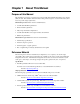
Chapter 1 About This Manual Purpose of this Manual This manual is for designers of systems based on the CoreModule™ 420 PC/104 single board computer (SBC) module. This manual contains information that permits designers to create an embedded system based on specific design requirements.
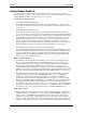
Chapter 1 About this Manual Related Ampro Products The following items are directly related to successfully using the Ampro product you have just purchased or plan to purchase. Ampro highly recommends that you purchase and utilize a CoreModule 420 QuickStart Kit simultaneously with the design of your product.
Chapter 1 About this Manual • MiniModule Family – This extensive line of peripheral interface modules, compliant with PC/104 and PC/104-Plus standard, can be used with Ampro’s CoreModule and LittleBoard single board computers to configure embedded system solutions. Ampro's highly reliable MiniModule products currently support USB 2.
Chapter 1 4 About this Manual Reference Manual CoreModule 420
Chapter 2 Product Overview This introduction presents general information about the PC/104 architecture and the CoreModule 420 single board computer (SBC). After reading this chapter you should understand: • PC/104 Concept • CoreModule 420 architecture • CoreModule 420 features • Major components • Connectors • Specifications PC/104 Architecture The PC/104 architecture affords a great deal of flexibility in system design.
Chapter 2 Product Overview Product Description The CoreModule 420 SBC is an exceptionally high integration, high-performance, 486-based PC compatible system in the PC/104 form factor. This rugged and high quality single board system contains all the component subsystems of a PC/AT motherboard plus the equivalent of several PC/AT expansion boards. In addition, the CoreModule 420 SBC includes a comprehensive set of system extensions and enhancements that are specifically designed for embedded systems.
Chapter 2 Product Overview • CompactFlash Socket ♦ Supports Type II PC card connector ♦ Supports IDE CompactFlash card ♦ Utilizes Secondary IDE bus • Floppy Disk Controller ♦ Shared connector with parallel port ♦ Supports two floppy drives ♦ Supports all standard PC/AT formats: 360kB, 1.2MB, 720kB, 1.44MB, 2.
Chapter 2 Product Overview • Video (LCD/CRT) Display Enhanced 2D graphics controller ♦ Supports BitBLT implementation for all 256 raster operations for Window support ♦ Supports all BLT transparency modes • Bitmap transparency • Pattern transparency • Source transparency • Destination transparency ♦ Supports 8, 16, 24, and 32-bit pixel depths ♦ Supports Hardware Clipping ♦ Supports fast line draw engine with Anti-aliasing ♦ Supports fast triangle fill engine ♦ Supports 4-bit Alpha blen
Chapter 2 Product Overview Block Diagram Figure 2-2 shows the functional components of the module. Memory (SDRAM) Video (CRT/TFT) Internal PCI Bus CPU Core Ethernet Controller STPC Atlas I2C Interface (Computer in a Chip) USB Port Speaker Serial Ports (Serial 1 & 2) HostPeripheral Interface GPIOs (8) IDE Devices (HDD, CompactFlash, CD-ROM, etc.
Chapter 2 Product Overview Major Integrated Circuits (ICs) Table 2-1 lists the major integrated circuits, including a brief description of each, on the CoreModule 420 and Figure 2-3 shows the location of the major chips. Table 2-1. Major Integrated Circuit Descriptions and Function Chip Type CPU (U14) Mfg. STMicroelectronics Model STPC ATLAS Description Embedded CPU – The combination of features in the CPU provide more than just a processor.
Chapter 2 Product Overview Connectors, Jumpers, and LEDs Connector Definitions Table 2-2 describes the connectors shown in Figures 2-4 to 2-6. Refer to Appendix B for part #s. Table 2-2. Module Connector Descriptions Jack/Plug # Access Description P1A/1B & P1C/1D – Top/ PC/104 Bus Bottom 104-pin connector used for PC/104 (ISA) bus J2 – Ethernet Top 8-pin, 0.1”, connector used for the Ethernet interface J3 – Serial 1 (COM1) Top 10-pin, 0.
Chapter 2 Product Overview Jumper Definitions Table 2-3 describes the jumpers shown in Figure 2-5. Table 2-3.
Chapter 2 Product Overview JP6 JP9 JP7 JP8 JP1 JP4 JP5 2 JP1 J5 1 JP6 J14 9 10 J3 JP5 JP4 U35 U3 JP9 U12 U36 JP7 L5 J11 2 1 3 J13 D8 J9 4 10 J4 1 J8 JP8 U7 2 U9 U8 U10 U41 U40 Bytewide Socket (U5) Pin-1 U6 U11 U5 D1 D2 U14 J2 U15 Link/Activity LED (D1) Speed LED (D2) U13 J10 J7 JP2 JP2 P1 CM420RFM_01c U16 Figure 2-5.
Chapter 2 Product Overview Specifications Physical Specifications Table 2-5 gives the physical dimensions of the module and Figure 2-7 gives the mounting dimensions. Table 2-5. Weight and Footprint Dimensions Item Dimension Weight Height (upper surface) 92.5g. (0.204lbs.) 10.99 mm (0.43 inches) See also Note on page 15. Width 90.2 mm (3.6 inches) Length 95.9 mm (3.
Chapter 2 Product Overview NOTE The CoreModule 420 is in violation of the PC/104 height limitations in two places on the bottom of the board. The voltage regulator (U19) exceeds the allowed height limitation by 0.085 inches and the CompactFlash socket (J12) exceeds the height limitation by 0.2 inches. See Figure 2-6. Power Specifications Table 2-6 provides the power requirements. Table 2-6.
Chapter 2 16 Product Overview Reference Manual CoreModule 420
Chapter 3 Hardware Overview This chapter discusses the chips and connectors of the module features in the following order: • CPU (U14) • Memory ♦ SDRAM (U7, U8, U9, U10) ♦ Flash Memory (U6) ♦ Bytewide socket (U5) • PC/104 (P1A, B, C, D) • IDE (J6) • CompactFlash (J12) • Serial (J3, J9, J13, J14) • Floppy/Parallel (J4) • Utility (J5) ♦ Keyboard ♦ Mouse ♦ Battery ♦ Reset Switch ♦ Speaker • Ethernet (J2) • USB (J10) • Video (J11) • Miscellaneous ♦ Time of Day/RTC ♦ User GPIO (J8) ♦ Oop
Chapter 3 Hardware CPU (U14) The CoreModule 420 uses an embedded microprocessor operating at 133MHz, that combines a powerful x86 core and a selection of peripheral interfaces into one chip. The STPC Atlas integrates a standard 5th generation x86 core. It supports logic including PC/104, UIDE controllers and combines these with standard I/O interfaces to provide a PC compatible subsystem in a single chip.
Chapter 3 Hardware Table 3-1.
Chapter 3 Hardware Interrupt Channel Assignments The channel interrupt assignments are shown in Table 3-2. Table 3-2. Interrupt Channel Assignments Device vs IRQ No. 0 Timer X 1 Keyboard 2 3 4 5 6 7 8 9 10 11 12 13 14 15 Disable X X Secondary Cascade COM1 D COM2 Z D Z COM3 O O O O O O O O D O O Z COM4 O O O O O O O D O O O Z Floppy D O Parallel O O O O Z O D RTC O O O Z X Prim. IDE D Z Sec.
Chapter 3 Hardware Address (hex) Subsystem 0040-0043 Programmable Interrupt Timer (Clock/Timer) 0060-0064 0070-0071 Keyboard Controller RTC/ NMI enable 0080-008F DMA Page 0094 Motherboard VGA enable 00A0-00A1 Slave Interrupt Controller (#2) 00C0-00DF Secondary DMA Controller (#2) 0102 VGA setup register 01F0-01F7 Primary IDE (configurable) 0170-0177 Secondary IDE (configurable) 0201 02E8-02EF Watchdog trigger (configurable, disabled by default) COM4 (configurable) 02F8-02FF COM2 (co
Chapter 3 Hardware PC/104 Bus Interface (P1A,B,C,D) The PC/104 Bus uses a 104-pin 0.1” connector interface. This interface connector will carry all of the appropriate PC/104 signals operating at clock speeds up to 8.25MHz. This interface connector is located on the both the top and bottom of the module. Table 3-5.
Chapter 3 Hardware Pin # Signal Description (P1 Row A) 27 (A27) SA4 System Address 4 – Refer to SA19, pin A12, for more information. 28 (A28) SA3 System Address 3 – Refer to SA19, pin A12, for more information. 29 (A29) SA2 System Address 2 – Refer to SA19, pin A12, for more information. 30 (A30) SA1 System Address 1 – Refer to SA19, pin A12, for more information. 31 (A31) SA0 System Address 0 – Refer to SA19, pin A12, for more information.
Chapter 3 Hardware Pin # Signal Description (P1 Row B) 49 (B17) DAck1* DMA Acknowledge 1 – Used by DMA controller to select the I/O resource requesting the bus, or to request ownership of the bus as a bus master device. Can also be used by the ISA bus master to gain control of the bus from the DMA controller. 50 (B18) DRQ1 DMA Request 1 – Used by I/O resources to request DMA service. Must be held high until associated DACK1 line is active.
Chapter 3 Hardware Pin # Signal Description (P1 Row C) 6 (C5) LA20 Lactchable Address 20 – Refer to LA23, pin C2, for more information. 7 (C6) LA19 Lactchable Address 19 – Refer to LA23, pin C2, for more information. 8 (C7) LA18 Lactchable Address 18 – Refer to LA23, pin C2, for more information. 9 (C8) LA17 Lactchable Address 17 – Refer to LA23, pin C2, for more information. 10 (C9) MemR* Memory Read – This signal instructs a selected memory device to drive data onto the data bus.
Chapter 3 Pin # Hardware Signal Description (P1 Row D) 31 (D10) DAck5* DMA Acknowledge 5 – Used by DMA controller to select the I/O resource requesting the bus, or to request ownership of the bus as a bus master device. Can also be used by the ISA bus master to gain control of the bus from the DMA controller. 32 (D11) DRQ5 DMA Request 5 – Used by I/O resources to request DMA service. Must be held high until associated DACK5 line is active.
Chapter 3 Hardware IDE Interface (J6) The IDE device signals are provided through the standard 44-pin, 2mm connector (J6). The IDE interface supports the following features: • Master mode PCI supporting Enhanced IDE devices • Supports two EIDE devices • Full scatter-gather capability • Supports ATAPI compliant devices including DVD • Supports IDE native and ATA compatibility modes Table 3-9 gives the signals for the 44-pins of the IDE 2mm header. Table 3-9.
Chapter 3 Hardware Pin # Signal Description 25 PIOR* Drive I/O Read – Strobe signal for read functions. Negative edge enables data from a register or data port of the drive onto the host data bus. Positive edge latches data at the host. 26 GND Digital Ground 27 IOChRdy I/O Channel Ready – When negated, extends the host transfer cycle of any host register access when the drive is not ready to respond to a data transfer request. High impedance if asserted.
Chapter 3 Hardware CompactFlash Socket (J12) The board contains a Type II PC card connector, which allows for the insertion of a CompactFlash card. The CompactFlash card acts as a standard IDE Drive and is connected as [CF on Sec Master] in BIOS. NOTE Supports True IDE Mode and Type 1 or Type II PC cards in the CompactFlash socket (J12). Table 3-10.
Chapter 3 Hardware Pin # Signal Description 24 NC Not connected – (IOCS16* = I/O select 16 bit) 25 GND Digital Ground 26 NC Not Connected (Card detect) 27 D11 Disk Data 11 – Refer to pin 2, D3, for more information. 28 D12 Disk Data 12 – Refer to pin 2, D3, for more information. 29 D13 Disk Data 13 – Refer to pin 2, D3, for more information. 30 D14 Disk Data 14 – Refer to pin 2, D3, for more information. 31 D15 Disk Data 15 – Refer to pin 2, D3, for more information.
Chapter 3 Hardware Floppy/Parallel Port (J4) Floppy Disk Drive Port The Super I/O chip provides the Floppy Disk Controller and the Parallel Port interface (J4). The Floppy Drive interface shares the same connector as the Parallel Port and the signals are multiplexed out of the connector. However, you can only use one of these devices at a time and it must be configured in BIOS Setup Utility. The default device in the BIOS Setup Utility is the Floppy Drive.
Chapter 3 Hardware Pin # Signal Description 8 SLIN Select In – This output signal is used to select the printer. I/O pin in ECP/EPP mode. STEP Step – Low step pulse for each track-to-track movement of the head. PD3 Parallel Port Data 3 – This pin (0 to 7) provides parallel port data signals. 9 RDATA Read Data – Raw serial bit stream from the drive for read operations. 10 GND Digital Ground 11 PD4 Parallel Port Data 4 – This pin (0 to 7) provides parallel port data signals.
Chapter 3 Hardware Serial Ports (J3, J9, J13, J14) The Atlas CPU and Super I/O chips each contain the circuitry for two of the four serial ports. The Atlas CPU provides serial port 1 (J3) and serial port 2 (J9) through the two independent 10-pin connectors. The Super I/O chip provides serial ports 3 (J13) and 4 (J14.
Chapter 3 Hardware Table 3-12. Serial Ports Pin/Signal Descriptions (J3, J9) Pin # Signal DB9 # Description 1 DCD* 1 Data Carrier Detect – Indicator to the serial port that external modem is detecting a carrier signal (i.e., a communication channel is currently open). In direct connect environments, this input will be driven by DTR as part of the DTR/DSR handshake.
Chapter 3 Hardware Pin # Signal DB9 # Description 4 RTS* 7 Request To Send – Indicates serial port is ready to transmit data. Used as hardware handshake with CTS for low level flow control. 5 TXD 3 Transmit Data – Serial port transmit data output is typically held to a logic 1 when no data is being sent. Typically, a logic 0 (On) must be present on RTS, CTS, DSR, and DTR before data can be transmitted on this line.
Chapter 3 Hardware Utility Interface (J5) The Utility interface consists of the 10-pin, 0.1” header on the module and is used as the interface for various utility signals. The Super I/O chip drives most of the device interfaces on the Utility interface. Table 3-15 shows the meaning of the interface signals for the utility interface.
Chapter 3 Hardware Ethernet Interface (J2) The Ethernet solution is provided by the Intel 82551ER PCI controller chip and consists of both the Media Access Controller (MAC) and the physical layer (PHY) combined into a single component solution. The 82551ER is a 32-bit PCI controller that features enhanced scatter-gather bus mastering capabilities, which enables the 82551ER to perform high-speed data transfers over the internal PCI bus.
Chapter 3 Hardware Video (LCD/CRT) Interface (J11) The STPC Atlas chip provides the 2D graphics controller for the video signals to a flat panel display and traditional glass CRT monitor.
Chapter 3 Hardware Table 3-17. Video Interface Pin/Signal Descriptions (J11) Pin # Signal Description TFTDCLK TFT Shift Clock – This clock signal provides the timing for transferring digital 1 pixel data. TFTDE TFT Data Enable – This signal indicates valid data on any of the FP [23:0] lines. 2 3 TFTLP TFT Line Pulse – This signal is the digital monitor equivalent of HSYNC. 4 TFTFrame TFT Frame Marker – This signal is the TFT monitor equivalent of VSYNC.
Chapter 3 Hardware Pin # Signal VSYNC 38 39 AGNDR Description Vertical Sync – This signal is used for the digital vertical sync output to the CRT. Also used (with HSYNC) to signal power management state information to the CRT per the VESA DPMS standard. Analog Ground for Red 40 RED Red – This pin provides the Red analog output to the CRT. 41 AGNDG Analog Ground for Green 42 GREEN Green – This pin provides the Green analog output to the CRT.
Chapter 3 Hardware Table 3-18. User GPIO Signals Pin/Signal Descriptions (J8) Pin # Signal Description 1 GPIO8 User defined 2 GPIO9 User defined 3 GPIO10 User defined 4 GPIO11 User defined 5 GPIO12 User defined 6 GPIO13 User defined 7 GPIO14 User defined 8 GPIO15 User defined 9 GND Ground 10 GND Ground Notes: The shaded area denotes ground.
Chapter 3 Hardware Serial Console BIOS Setup The serial console feature may be invoked by entering the appropriate option (port selected) in the Serial Console field of the BIOS and Hardware Settings screen in BIOS Setup. A standard null modem serial cable is used to connect the chosen serial port on the CoreModule 420 (J3 or J9) to a serial terminal or PC.
Chapter 3 Hardware • Watchdog Code examples – Ampro has provided source code examples on the CoreModule 420 Doc & SW CD-ROM illustrating how to control the WDT. The code examples can be easily copied to your development environment to compile and test the examples, or make any desired changes before compiling. Refer to the WDT Readme file in the Miscellaneous Source Code Examples subdirectory, under the Support Software menu on the CoreModule 420 Doc & SW CD-ROM.
Chapter 3 44 Hardware Reference Manual CoreModule 420
Chapter 4 BIOS Setup Introduction This chapter describes the BIOS Setup menus and the various screens used for configuring the CoreModule 420. Some features in the Operating System or application software may require configuration in the BIOS Setup screens. This section assumes the user is familiar with general BIOS setup and does not attempt to describe the BIOS functions. Refer to the appropriate PC reference manuals for information about the software interface of the onboard ROM-BIOS.
Chapter 4 BIOS Setup Accessing BIOS Setup (Serial Console) Entering the BIOS Setup, in serial console mode, is very similar to the steps you use to enter BIOS Setup with a VGA display input, except the actual keys you use. 1. Connect the serial console, or the PC with serial terminal emulation, to Serial Port 1 (J3) or Serial Port 2 (J9) of the CoreModule 420. ♦ If the BIOS option, Serial Console is set to [Enable], use a standard null-modem serial cable.
Chapter 4 BIOS Setup Main BIOS Setup Menu Ampro Setup Utility for CoreModule 420, SWxxxxxx Help for BIOS and Hardware Settings > BIOS and Hardware Settings < Reload Initial Settings Load Factory Default Settings Exit, Saving Changes Exit, Discarding Changes Use Arrow keys to change menu item, use Enter to select menu item (C) Copyright 2004, Ampro Computers, Inc. - http://www.ampro.com Figure 4-1.
Chapter 4 BIOS Setup BIOS Configuration Screen Ampro Setup Utility for CoreModule 420, SWxxxxxx [Date & Time] > Date 16 Feb 2004< Time 10:24:34 [Drive Assignment] Drive A 1.44 MB, 3.5” Drive B (none) Drive C HDD on Pri Master Drive D (none) Drive E (none) [Boot Order] Boot 1st Drive A: Boot 2nd Drive C: CDROM Boot 3rd Boot 4th (none) Boot 5th (none) Boot 6th (none) [Drive and Boot Options] Help for Date The Date & Time fields are updated in real-time.
Chapter 4 BIOS Setup • Boot Order ♦ Boot 1st – [none], [Drive A], [Drive B], [Drive C], [Drive D], [CDROM], [Alarm], [Reboot], or [Flash] ♦ Boot 2nd – [none], [Drive A], [Drive B], [Drive C], [Drive D], [CDROM], [Alarm], [Reboot], or [Flash] ♦ Boot 3rd – [none], [Drive A], [Drive B], [Drive C], [Drive D], [CDROM], [Alarm], [Reboot], or [Flash] ♦ Boot 4th – [none], [Drive A], [Drive B], [Drive C], [Drive D], [CDROM], [Alarm], [Reboot], or [Flash] ♦ Boot 5th – [none], [Drive A], [Drive B], [Drive C
Chapter 4 BIOS Setup • Keyboard and Mouse ♦ Numlock – [Disabled] or [Enabled] ♦ Typematic – [Disabled] or [Enabled] • Delay – [250ms], [500ms], [750ms], or [1000ms] This feature is used for the keyboard and determines the typing delay. • Rate – [30cps], [24cps], [20cps], [15cps], [12cps], [10cps], [8cps], or [6cps] This feature is used for the keyboard and determines the typing rate.
Chapter 4 BIOS Setup This feature, if enabled by selecting a timer interval, will direct the watchdog timer to reset the system if it fails to boot the OS properly. ♦ Serial Console – [Hot Cable] or [Enabled] ∗ The Hot Cable option only allows console redirection when a Hot Cable is actually connected to Serial 1 or 2 (COM 1 or 2). The Hot Cable option can not be used on Serial 3 or 4 (COM 3 or 4). Use the modified serial cable described in Chapter 3, under Hot (Serial) Cable.
Chapter 4 BIOS Setup ♦ USB IRQ – [none], [1], [3], [4], [5], [6], [7], [9], [10], [11], [12], [14], or [15] ♦ Ethernet IRQ – [none], [1], [3], [4], [5], [6], [7], [9], [10], [11], [12], [14], or [15] ♦ ISA Speed – [7.16 MHz] or [8.
Chapter 4 BIOS Setup Splash Screen Customization The CoreModule 420 BIOS supports a graphical splash screen, which can be customized by the user and displayed on screen when enabled through the BIOS Setup Utility. The graphical image can be a company logo or any custom image the user wants to display during the boot process. The custom image can be displayed as the first image displayed on screen during the boot process and remain there, depending on the options selected in BIOS Setup, while the OS boots.
Chapter 4 BIOS Setup Use the following steps to convert and load your custom image onto the CoreModule 420. 1. Copy the files from the CM420\software\examples\splash directory on the CD-ROM to a new directory (conversion directory) on your PC. This new conversion directory is where you intend to do the conversion and save the file. 2. Ensure you remove the read-only attributes from all the files as part of the file copying process. 3. Copy the CoreModule 420 BIOS binary file (cm420.
Chapter 4 BIOS Setup On-Board Flash Access and Use This section describes how to use the on-board flash memory and load an application in the available lower 768kB region of the 1MB of Flash Memory. The application can boot directly from the on-board flash memory. The Flash memory can be accessed at 128MB intervals above the base address (with the exception of 256MB). For example, if the Flash address is set to 8MB, then the Flash memory can be accessed at 136MB, 392MB, 520MB etc.
Chapter 4 BIOS Setup Example Assumptions The following assumptions have been made concerning the application and certain functionality has not implemented. • The application is located at the fixed address of 1MB • The bootloader has to load the application at the fixed address of 1MB • The startup code is incomplete For example, early initialization functions and constructors normally called before main, are not called at all.
Appendix A Technical Support Ampro Computers, Inc. provides a number of methods for contacting Technical Support listed below in Table A-1. Requests for support through the Virtual Technician are given the highest priority, and usually will be addressed within one working day. • Ampro Virtual Technician – This is a comprehensive support center designed to meet all your technical needs. This service is free and available 24 hours a day through the Ampro web site at http://ampro.custhelp.com.
Appendix A 58 Technical Support Reference Manual CoreModule 420
Appendix B Connector Part Numbers These connectors are used on the CoreModule 420 and can be used to determine the mating connectors, if you want to make your own cables. Table B-1. Connector and Manufacture’s Part Numbers Connector Pin Number/Pin Spacing/ Orientation Manufacturer Manufacturer’s PN J2 – Ethernet 8-pin, 0.1”, right angle Molex Housing = 10-11-2063 Pins = 08-55-0102 J3 – Serial 1 10-pin, 0.1”, right angle Molex 10-89-1106 J4 – Floppy/ Parallel 26-pin, 0.
Appendix B 60 Connector Part Numbers Reference Manual CoreModule 420
Index Accessing BIOS Setup (Serial Console) .............. 46 Accessing BIOS Setup (VGA)............................. 45 Ampro Products CoreModule 410............................................. 2 CoreModule 420............................................. 6 CoreModule 600............................................. 2 EnCore Family ............................................... 3 LittleBoard Family ......................................... 2 MiniModule Family .......................................
Index power requirements..........................................15 QuickStart Kit ....................................................2 Real Time Clock (RTC) ...................................40 RS485 mode.....................................................34 serial connectors...............................................34 serial console option.........................................41 serial port features............................................33 single board computer (SBC).....................
Index Serial terminal ANSI-compatible ............................................. 41 serial port settings ............................................ 42 Speaker connector pin outs ............................................ 36 supported feature.............................................. 36 Splash screen converting image.............................................. 53 customization ................................................... 53 customer defined..............................................
Index 64 Reference Manual CoreModule 420