
Computer Hardware User Manual


CoreModule 420 Reference Manual 17
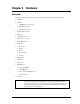
Chapter 3 Hardware
Overview
This chapter discusses the chips and connectors of the module features in the following order:
• CPU (U14)
• Memory
♦ SDRAM (U7, U8, U9, U10)
♦ Flash Memory (U6)
♦ Bytewide socket (U5)
• PC/104 (P1A, B, C, D)
• IDE (J6)
• CompactFlash (J12)
• Serial (J3, J9, J13, J14)
• Floppy/Parallel (J4)
• Utility (J5)
♦ Keyboard
♦ Mouse
♦ Battery
♦ Reset Switch
♦ Speaker
• Ethernet (J2)
• USB (J10)
• Video (J11)
• Miscellaneous
♦ Time of Day/RTC
♦ User GPIO (J8)
♦ Oops! Jumper (BIOS Recovery)
♦ Watchdog timer
• Power (J7)
NOTE Ampro Computers, Inc. only supports the features/options tested and listed in this
manual. The main integrated circuits (chips) used in the CoreModule 420 may
provide more features or options than are listed for the CoreModule 420, but some
of these features/options are not supported on the module and will not function as
specified in the chip documentation.