CoreModule™ 800 PCI-104 Single Board Computer QuickStart Guide P/N 5001756A Revision A
Notice Page NOTICE No part of this document may be reproduced, transmitted, transcribed, stored in a retrieval system, or translated into any language or computer language, in any form or by any means, electronic, mechanical, magnetic, optical, chemical, manual, or otherwise, without the prior written permission of Ampro Computers, Incorporated.
Contents Chapter 1 Setting Up the CoreModule 800.................................................................................... 1 Using this Guide ................................................................................................................................. 1 Requirements................................................................................................................................. 1 What’s in the Box ..................................................................
Contents Table A-1. Technical Support Contact Information..........................................................................21 Table B-1. I/O Interface Board Jumper (JP1) Settings....................................................................23 Table B-2. Utility 1a Interface Pin/Signal Descriptions (J4).............................................................24 Table B-3. Utility 2a Interface Pin/Signal Descriptions (J5).............................................................
Chapter 1 Setting Up the CoreModule 800 Using this Guide This guide provides the most efficient way to set up your CoreModule™ 800 SBC (single board computer).
Chapter 1 Setting Up the CoreModule 800 Setup Steps It is important to follow the setup steps in this section in the exact order listed here, but skip any steps that do not apply to your situation. References are provided to chapters within this guide or other Ampro guides, for more information about installation and use of this CoreModule 800.
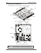
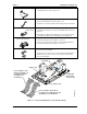
Chapter 1 Setting Up the CoreModule 800 Connecting Cables to the CoreModule 800 CoreModule 800 Utility 2 (J5) Daughter Power Board Utility 1 (J4) CM800QkS_03a Connect the cables provided with the CoreModule 800 QuickStart Kit to the respective connectors on the CoreModule 800 SBC. Skip any cable(s) that do not apply to your situation. Video (J1) IDE (J6) Ethernet (J3) Power In (J7) Figure 1-1.
Chapter 1 Setting Up the CoreModule 800 Skip any steps that do not apply to your situation. • Connect Utility 1 cable to J4 on the CoreModule 800 as shown in Figure 1-3. 1) Connect Utility 1 & 2 Cables • Connect Utility 2 cable to J5 on the CoreModule 800 as shown in Figure 1-3. Utility 1 and 2 cables are identical and can be interchanged. • Connect the IDE cable to J6 on the CoreModule 800 as shown in Figure 1-3.
Chapter 1 Setting Up the CoreModule 800 3) Connect the Video Cable • Connect the Video cable to the Video connector (J1) on the CoreModule 800 as shown in Figure 1-4. Pin-1 4) Connect Power Adapter Cable • Connect the Power Adapter Cable to the Power In connector (J7) on the CoreModule 800 as shown in Figure 1-4. See Table 1-2 for Power Adapter Cable wiring and pin connections.
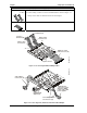
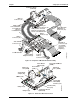
Chapter 1 Setting Up the CoreModule 800 I/O Interface Board (I/O Board) Utility 1a Connector (J4) Utility 1 Cable connected between J4 on I/O Board and J4 on CoreModule 800 Utility 2a Connector (J5) Floppy Disk Drive (FDD) Cable & Connectors (J11) Utility 2 Cable connected between J5 on I/O Board and J5 on CoreModule 800 Utility 2 Connector (J5) Utility 1 Connector (J4) Video Cable & Connectors (J1) IDE Cable & Connectors (J6) (Second IDE connector not shown for simplicity.
Chapter 1 Setting Up the CoreModule 800 Connecting Peripherals 8) Connect peripheral I/O devices to the I/O Board. This includes the keyboard, mouse, and CRT. Skip any devices that are not applicable to your situation. • Connect the keyboard to the keyboard connector (J9A) on the I/O Board (lower connection). Or, Connect a USB keyboard to one of the USB ports on the I/O Board. • Connect the mouse to the PS/2 connector (J9B) on the I/O Board.
Chapter 1 Setting Up the CoreModule 800 Connecting the Power Supply 12) Connect the Power Supply • Connect the AT power supply to the power adapter cable connected to J7 on the CoreModule 800. The available connector mates with the standard power connectors used for hard disk drives on AT or ATX power supplies.
Chapter 1 Setting Up the CoreModule 800 18) Enter BIOS Setup • Press the key early in the boot process to enter BIOS Setup. • Use BIOS Setup during the initial boot to set the desired options (time and date, alter the boot order for the floppy drive, CD-ROM, hard disk drive, or select Network: (LAN Boot), etc.). • Refer to Step 19 to alter the boot sequence, while in BIOS Setup. 19) Alter Boot Order, only if needed.
Chapter 1 Setting Up the CoreModule 800 f) For LAN Boot, go to PXE Boot Agent BIOS Setup after rebooting • Enter PXE BIOS by pressing Ctrl + S, when you see the following prompt appear on screen: Initializing Intel (R) Boot Agent FE v4.x.xx PXE v2.0 Build 084 (WfM 2.0) Press Ctrl + S to enter the setup Menu.. • Make the necessary changes in the PXE BIOS Setup before saving changes. Refer to Appendix C of the CoreModule 800 Reference Manual for more information.
Chapter 1 Setting Up the CoreModule 800 J4 Flat Panel Voltage Select (JP4) J5 D9 D10 JP3 D17 JP4 U1 Serial 1 RS-485 Termination (JP3) U2 J1 J9 U9 U11 J3 U26 Q1 J8 Q6 U5 U13 U12 Q2 Q3 J6 J7 JP1 CMOS Normal/ Clear (JP1) JP2 Serial 2 RS-485 Termination (JP2) CM800QkS_01b Q4 Figure 1-8. CoreModule 800 Jumper Locations The power adapter cable is connected between the Power In connector (J7) and the power supply connector. See Steps 5 and 12. Table 1-2.
Chapter 1 12 Setting Up the CoreModule 800 QuickStart Guide CoreModule 800
Chapter 2 Installing CoreModule 800 Options The procedures in the first part of this chapter describe how to install or remove the CoreModule 800 SBC (Single Board Computer) options onto or from the board, including the SODIMM card. Brief instructions for loading supported Operating Systems and accessing the CoreModule 800 Doc & SW (Documentation and Software) CD-ROM are also provided at the end of this chapter.
Chapter 2 Installing CoreModule 800 Options To prevent damage to the CoreModule 800 or the SODIMM, do not touch the either one until you have discharged yourself and have followed good Electrostatic Discharge principals. The CoreModule 800 and the SODIMM are sensitive to static electricity and can be easily damaged by improper handling. Do the following when handling either one: CAUTION Use an anti-static wrist/ankle strap and a grounding mat connected to ground.
Chapter 2 Installing CoreModule 800 Options DDR SODIMM DDR SODIMM Socket (J13) CM800QkS_09a 45° Angle Figure 2-2. Removing SODIMM from Socket Installing the SODIMM If you want to install a different size SODIMM or replace the existing SODIMM, refer to the following procedure. 1. Prepare the CoreModule 800 for SODIMM installation: ♦ If the CoreModule 800 is already prepared for SODIMM installation, with the power turned off, the power cord disconnected, and an empty SODIMM socket, skip to Step 4.
Chapter 2 Installing CoreModule 800 Options 4. Turn the CoreModule 800 over to access the bottom of the board and lay it on a flat anti-static surface. See Figures 2-1 and 2-3. 5. Remove the existing SODIMM from the SODIMM socket before continuing. Refer to the Step 4 in the proceeding procedure, Removing the SODIMM, and follow the remaining steps in that procedure before continuing with the next step in this procedure. 6.
Chapter 2 Installing CoreModule 800 Options Press down on SODIMM at both corners until you hear a snap. CM800QkS_11a DDR SODIMM Figure 2-4. Pressing down on SODIMM 10. If the retaining latches do not close completely on the SODIMM, remove it and repeat Steps 7 to 9. 11. Turn the CoreModule 800 back over onto the bottom of the board, placing it on the work surface. 12. Reconnect any cables you disconnected earlier and verify all other connections to the CoreModule 800 are still connected. 13.
Chapter 2 Installing CoreModule 800 Options Installing Software, Drivers, and Utilities To install the operating system and respective software drivers, refer to the following procedure. 1. Install the desired operating system (OS) and related drivers from the source files (LAN Boot) or from the manufacturer’s diskette(s) or CD-ROM. If you are using the LAN Boot feature to load the boot (OS) image, skip the remaining Steps that do not apply.
Chapter 2 Installing CoreModule 800 Options There are directories and subdirectories under these topics that should provide you with the needed manuals, utilities, and tools not explained earlier. 4. Install any special OS drivers not found on the manufacturer’s diskette(s) or CD-ROM. Refer to the directories and subdirectories on the CoreModule 800 Doc & SW CD-ROM for instructions when installing the drivers for the desired OS.
Chapter 2 20 Installing CoreModule 800 Options QuickStart Guide CoreModule 800
Appendix A Technical Support Ampro Computers, Inc. provides a number of methods for contacting Technical Support listed below in Table A-1. Requests for support through the Virtual Technician are given the highest priority, and usually will be addressed within one working day. • Ampro Virtual Technician – This is a comprehensive support center designed to meet all your technical needs. This service is free and available 24 hours a day through the Ampro web site at http://ampro.custhelp.com.
Appendix A 22 Technical Support QuickStart Guide CoreModule 800
Appendix B I/O Interface Board Overview The I/O Interface Board (I/O Board) provides the I/O device connections and interface to the CoreModule 800 in the Utility connectors (J4, J5) on the I/O Interface Board. The I/O Interface Board (I/O Board) provides the I/O connections for the keyboard, mouse, floppy/parallel port, serial ports (2) and USB ports (2).
Appendix B I/O Interface Board I/O Interface Board Connectors Table B-2 lists the interface between Utility 1a (J4) and the other connectors/devices on the I/O Board. Table B-2. Utility 1a Interface Pin/Signal Descriptions (J4) J4 Signal Pin # Pin # On- Description board 1 J7-1 Data Carrier Detect 0 – Indicates external serial device is detecting a carrier signal (i.e., a communication channel is currently open).
Appendix B I/O Interface Board J4 Signal Pin # Pin # On- Description board 14 RTS1* J7-16 Request To Send 1 – Indicates serial port is ready to transmit data. Used as hardware handshake with CTS1 for low level flow control. 15 TXD1 (through JP1) J7-12 Transmit Data 1 Output – This line is typically held to a logic 1 when no data is being sent. A logic 0 (On) must be present on RTS1, CTS1, DSR1, and DTR1 before transmitting data on this line.
Appendix B I/O Interface Board Table B-3 lists the interface between Utility 2a (J5) and the other connectors/devices on the I/O Board. Table B-3. Utility 2a Interface Pin/Signal Descriptions (J5) J5 Signal Pin # 1 Description STB* J12-1 Parallel Strobe* – Output used to strobe data into the printer. I/O pin in ECP/EPP mode.
Appendix B I/O Interface Board J5 Signal Pin # OnBoard Pin # Description 17 PD7 J12--17 18 GND GND Ground 19 ACK* J12-19 Parallel Acknowledge – Status output signal from the printer. A Low State indicates it data received and is ready to accept new data. DS1 J11-12 Floppy Drive Select 1 – Selects drive 1. 20 GND GND Ground 21 BSY J12-21 Parallel Busy – Status output signal from the printer. A High State indicates the printer is not ready to accept data.
Appendix B I/O Interface Board Table B-4 lists the connections on the I/O Board between the Serial Port 1 connector (J7) and the Utility 1Connector (J1). Table B-4. Serial Port 1 Interface Pin/Signal Descriptions (J7B) J7 Signal Pin # From Description Onboard Connector & Pin # 1 DCD1* J4-1 Data Carrier Detect 1 – Indicates external serial device is detecting a carrier signal (i.e., a communication channel is currently open).
Appendix B I/O Interface Board Table B-5 lists the connections on the I/O Board between Serial Port 2 connector (J7A) and the Utility 1a interface connector (J4) or other connections on the board. Table B-5. Serial Port 2 (COM2) Interface Pin/Signal Descriptions (J7A) J7A Pin # Signal From Onboard Connector & Pin # 1 DCD2* J4-11 Data Carrier Detect 2 – Indicates external serial device is detecting a carrier signal (i.e., a communication channel is currently open).
Appendix B I/O Interface Board Table B-6. Miscellaneous Interface Pin/Signal Descriptions (J6) J6 Signal Pin # From Onboard Description Connector & Pin # 1 PS_ON J4-10 Power Supply On – This signal from the I/O hub on CoreModule 800 can be used to turn on a power supply. 2 EXTSMI* J4-36 External SMI – External System Management Interrupt (SMI) signal from an external source is fed directly to the I/O Hub.
Appendix B I/O Interface Board Table B-9. Mouse Interface Pin/Signal Descriptions (J9B) J9B Signal Pin # From Onboard Connector & Pin # Description J4-31 Mouse Data 1 MSDAT 2, 4 NC 3 GND J5-37 Ground 5 KBVCC J5-38 Mouse Power (+5V +/-5%) – Provided through shared Fuse (F1) to mouse voltage pin. 6 MSCLK J4-32 Mouse Clock NA Not connected Note: The shaded area denotes power or ground. Table B-10.
Appendix B I/O Interface Board Table B-11. Floppy Drive Interface Pin/Signal Descriptions (J11) Pin # Signal Description 2 DRVEN0 Drive Density Select 0 – This signal indicates a low (250/300 kbps) or high (500 kbps) data rate has been selected. 4 NC Not connected 6 NC Not connected 8 INDEX Index – Detects the drive head is positioned over the track 0. 10 NC Not connected (MTR0 - Motor Control 0) 12 DS1 Drive Select 1 – Selects drive 1.
Appendix B I/O Interface Board Table B-12. Parallel Port (LPT) Interface Pin/Signal Descriptions (J12) Pin # Signal Description 1 Strobe* Strobe* – This is an output signal used to strobe data into the printer. I/O pin in ECP/EPP mode. 2 PD0 Parallel Port Data 0 – These signals <0 to 7> provide the parallel port data signals 3 PD1 Parallel Port Data 1 – Refer to pin-2 for more information. 4 PD2 Parallel Port Data 2 – Refer to pin-2 for more information.
Appendix B I/O Interface Board Miscellaneous Components Table B-13 list the helpful components on the I/O Interface Board. Table B-13. Miscellaneous Components Component Description Battery Battery Socket (BAT1) – Supports external Lithium (3.0V) battery for the Real Time Clock on CoreModule 800. Fuse (F1) Auto-reset, 1.5 Amp shared fuse for keyboard and mouse. LED (D1) Green Hard Disk Drive Activity LED (D1) – Indicates activity on the IDE connector (J6) located on the CoreModule 800.
Appendix C Connector Part Numbers The following tables provide the connectors, including the manufacturers and part numbers for the used on the CoreModule 800, I/O Board, or Cable Adapter Board. These part numbers can be used to determine the mating connectors, when making your own cables. All connectors use 0.100" (2.54 mm) pin spacing unless otherwise indicated. Table C-1.
Appendix C 36 Connector Part Numbers QuickStart Guide CoreModule 800