
Specifications


Software Configuration
3–23
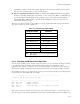
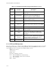
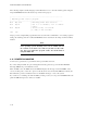
Table 3–7 Parallel Port Register Bits
Register
Bit
Signal Name
or Function
In/Out
Active
High/Low
J15
Pin
DB25F
Pin
DATA
(378h)
(278h)
0
1
2
3
4
5
6
7
Data 0
Data 1
Data 2
Data 3
Data 4
Data 5
Data 6
Data 7
I/O
I/O
I/O
I/O
I/O
I/O
I/O
I/O
High
High
High
High
High
High
High
High
3
5
7
9
11
13
15
17
2
3
4
5
6
7
8
9
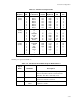
STATUS
(379h)
(279h)
0
1
2
3
4
5
6
7
TMOUT
0
0
-ERROR
SLCT
PE
-ACK (IRQ)
BUSY
In
---
---
In
In
In
In
In
---
---
---
Low
High
High
Low
High
---
---
---
4
25
23
19
21
---
---
---
15
13
12
10
11
CONTROL
(37Ah)
(27Ah)
0
1
2
3
4
5
6
7
-STROBE
-AUTOFD
-INIT
SLC
IRQE
PCD
1
1
Out*
Out*
Out*
Out*
---
---
---
---
Low
Low
High
High
High
High
---
---
1
2
6
8
---
---
---
---
1
14
16
17
---
---
---
---
* Can also be used as input (see text).
Parallel port register bit definitions:
Table 3–8 Standard and PS/2 Mode Register Bit Definitions
Signal
Name
Full Name
Description
TMOUT Time-out Valid only in EPP mode , this signal goes true
after a 10 μS time-out has occurred on the
EPP bus. This bit is cleared by reset.
-ERR Error Reflects the status of the -ERROR input. 0
means an error has occurred.
SLCT Printer selected
status
Reflects the status of the SLCT input. 1 means
a printer is on-line.