
Specifications
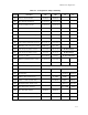


Hardware Configuration
2–7
can connect a +12V supply to the Little Board module through the power connector, J10. This will
supply +12V to the ISA and PCI portions of the PC/104 expansion busses. Similarly, you can connect
-12V to J16, the Utility Connector, to supply those voltages to both expansion busses, and -5V to J16 to
supply -5V. Pinouts for the Utility Connector are provided in Table 2–36.
If a PCI expansion card requiring 3.3V is installed, that voltage can be connected to J10-5 to supply
power to J21, the PCI bus interface connector.
Switching Power Supplies
If you use a switching power supply, be sure it regulates properly with the load your system draws. Some
switching power supplies do not regulate properly unless they are loaded to some minimum value. If this
is the case with your supply, consult the manufacturer about additional loading, or use another supply or
another type of power source (such as a linear supply, batteries, etc.). The minimum power for the Little
Board/P5i appears in the power specifications in Chapter 1.
2.2.2 Powerfail Options
The Little Board/P5i includes a circuit that can sense a power failure. If the +5V power supply falls
below 4.7 V, the powerfail logic produces a non-maskable interrupt (NMI). If it falls below 4.4V, it
generates a hard reset.
Non-maskable interrupt (NMI): When the supply voltage falls below (approximately) 4.7 volts, the
powerfail logic sends an NMI to the CPU. If you want a response to the NMI, you can provide an NMI
handler in your application, and patch the NMI interrupt vector address to point to your routine. See
Chapter 3 for additional information about writing an NMI handler for the powerfail interrupt.
If you have configured the byte-wide socket S0 for battery backup, it will be write protected while power
is below 4.75 volts. (Its chip select is held to a logic 1.) This is to prevent writing bad data to an SRAM
in S0 when the voltage is low.
Hardware reset: If the supply voltage falls below (approximately) 4.4V, the powerfail logic initiates a
hardware reset (like pressing the RESET button). A “clean” reset during a low voltage period prevents
erratic operation or crashes. Reset is asserted for the duration of the low-voltage period plus ~200 mS
after the voltage returns to above 4.4V.
2.2.3 Backup Batteries
Real-Time Clock Battery
The real-time clock backup battery on the Little Board/P5i should last 10 years under normal usage.
Byte-wide Socket Backup Battery for SRAMs
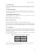
You can connect an external 3.6V lithium battery to convert an SRAM in byte-wide socket to a non-
volatile RAM (NOVRAM). When selecting a backup battery, calculate the battery life using the
following formula.
Battery life = (BAT mA-h
÷ SRAM backup current) × Duty Cycle
To calculate battery life, divide the milliamp-hour battery rating by the SRAM backup current rating.
Then, multiply that result by the duty cycle of the battery. That is, estimate the percentage of time the
battery supplies power (while the system is off).
Connect the positive terminal of the battery to the Utility Connector, J16, pin 15 and the negative
terminal to J16-16.