
Specifications


Hardware Configuration
2–15
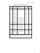
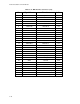
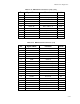
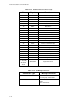
Table 2–10 Parallel Port Connector (J15)
J15
Pin
Signal
Name
Function
In/Out
DB25
Pin
1
3
5
7
9
11
13
15
17
19
21
23
25
STROBE*
Data 0
Data 1
Data 2
Data 3
Data 4
Data 5
Data 6
Data 7
ACK*
BUSY
PAPER OUT
SEL OUT
Output data strobe
LSB of printer data
MSB of printer data
Character accepted
Cannot receive data
Out of paper
Printer selected
OUT
I/O
I/O
I/O
I/O
I/O
I/O
I/O
I/O
IN
IN
IN
IN
1
2
3
4
5
6
7
8
9
10
11
12
13
2
4
6
8
26
AUTOFD*
ERROR
INIT*
SEL IN
N/A
Autofeed
Printer error
Initialize printer
Selects printer
Key pin
OUT
IN
OUT
OUT
14
15
16
17
10,12,
14,16
18,20
22,24
GROUND
Signal ground
N/A
18-25
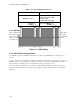
Data lines: 24 mA sink (.4 V max.), 12 mA source (2.4 V min.).
Control lines: 24 mA sink (.4 V max.), open collector with 4.7K pull-
ups.