
User Guide


Chapter 3 Hardware
22 Reference Manual MightyBoard 821
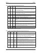
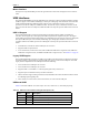
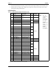
Note: The shaded area denotes power or ground.
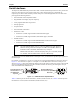
Audio Interface
The audio solution on the MightyBoard 821 is provided by the I/O Hub, 82801DBM (Southbridge) and the
on-board Audio CODEC (ALC202A). These two chips use a digital interface to communicate between the
two, which is defined by AC’97 and is revision 2.3 compliant. The input or output signals for the audio
interface go through the 14-pin jack (J14), which has the respective audio connections.
Audio CODEC (ALC202A) features
• AC’97 Rev 2.3 compliant
• 18-bit full duplex performance
• Variable sampling rate at 1Hz resolution
• Stereo (Left and Right) Line In
• Stereo (Left and Right) Line Out
• Microphone (mono) in
• PC Beep speaker signal also fed to CODEC for the Line Out (Left and Right) channels
Video Interfaces
The Memory Hub, 82915GM (Northbridge) provides the graphics control and video signals to the
traditional CRT monitors and the LVDS flat panel displays. The Memory Hub (Northbridge) features are
listed below:
Supports 2D/3D graphics with extensive set of instructions including:
• 3D rendering and display
• BLT operations
• MPEG2 decode acceleration
• 3D overlay
CRT features:
• Supports an integrated 400-MHz, 24-bit RAMDAC to drive a progressive scan analog monitor and
outputs to three 8-bit DACs provide the R, G, and B signals to the monitor
• Supports resolutions up to 1600 x 1200 at 85-Hz refresh, or up to 2048x1536 at 75-Hz refresh
• Supports a maximum allowable video frame buffer size of 64MB UMA (Unified Memory Architecture)
LVDS Flat Panel features:
• Supports an integrated dual channel LFP Transmitter interface
• Supports LVDS LCD panel resolutions up to UXGA
• Supports a maximum pixel format of 18 bpp (with SSC supported frequency range from 25 MHz to 112
MHz (single channel/dual channel)
• Supports 1 or 2 channel LVDS outputs
• The 82915GM chip only supports the LVDS port on Pipe B of two pipelines
• Supports the LVDS port independently or simultaneously with the Analog Display (CRT) port
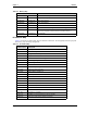
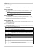
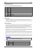
6 USBP4+ Universal Serial Bus 3 Positive
7, 8, 9, 10
GND Ground
Table 3-6. USB Ports 4 & 5 Interface Pin/Signal Descriptions (J21) (Continued)