99 Washington Street Melrose, MA 02176 Phone 781-665-1400 Toll Free 1-800-517-8431 Visit us at www.TestEquipmentDepot.
AMP-25 AMP-25-EUR User Manual 1/2015, 6004363 B ©2015 Amprobe®` Test Tools. All rights reserved.
Limited Warranty and Limitation of Liability Your Amprobe product will be free from defects in material and workmanship for one year from the date of purchase unless local laws require otherwise. This warranty does not cover fuses, disposable batteries or damage from accident, neglect, misuse, alteration, contamination, or abnormal conditions of operation or handling. Resellers are not authorized to extend any other warranty on the behalf of Amprobe.
AMP-25 / AMP-25-EUR Mini-Clamp CONTENTS SYMBOL................................................................................ 3 SAFETY INFORMATION........................................................ 4 UNPACKING AND INSPECTION............................................ 6 MEASUREMENTS.................................................................. 6 Measuring AC and DC Current....................................... 8 DC A ZERO.......................................................................
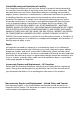
AMP-25 / AMP-25-EUR Mini-Clamp 1 5 2 TRMS AC / 3 ZERO 2 Sec 6 4 AMP-25 1 Jaw 2 Hand Guard 3 Jaw Trigger 4 LCD Display 5 Indicator of the Jaw Center for Current Measurement 6 Backlight / Flashlight & Function Buttons
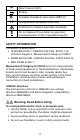
16 15 14 13 7 8 12 9 10 11 7 AUTO: Auto AC/DC current measurement mode active 8 Non-Contact Voltage mode active 9 Negative reading 10 Battery status indicator 11 A: Amps 12 Alternating Current (AC) Direct Current (DC) 13 HOLD: Data hold 14 LPF: Low Pass Filter mode active 15 INRUSH: Inrush current mode active 16 ∆ Relative ZERO is active Symbols Application and removal from hazardous live conductors permitted Caution! Risk of electric shock W Caution! Refer to the explanation in this
F Direct Current (DC) Battery ) Canadian Standards Association (NRTL/C) P Complies with European Directives Conforms to relevant Australian standards = Do not dispose this product as unsorted municipal waste. Contact aqualified recycler SAFETY INFORMATION The Meter complies with: • UL/IEC/EN 61010-1, CAN/CSA C22.2 No. 61010-1-12, Pollution Degree 2, Measurement Category III 600 V • IEC/EN 61010-2-032, CAN/CSA-C22.2 No.
• Do not use the Meter if it appears damaged. Inspect the Meter before use. Look for cracks or missing plastic. Pay particular attention to the insulation around the connectors. • Have the Meter serviced only by qualified service personnel. • Use extreme caution when working around bare conductors or bus bars. Contact with the conductor could result in electric shock. • Do not hold the Meter anywhere beyond the tactile barrier. • When measuring current, center the conductor in the clamp.
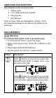
Unpacking and Inspection Your shipping carton should include: 1 Clamp meter 2 1.5 V LR44 batteries (installed) 1 Carrying case 1 User Manual If any of these items are damaged or missing, return the complete package to the place of purchase for an exchange. MEASUREMENTS � Warning To avoid possible electric shock or personal injury: • To avoid electric shock or personal injury: • When measuring current, center the conductor in the clamp. • Keep fingers behind Tactile Barrier.
Press button to select AC A or DC A mode. Press button > one second to return to AUTO AC/DC A mode. Press button to enter Low Pass Filter mode (LPF is displayed). Press a second time to enter Inrush mode (INRUSH is displayed). Press again to exit the function. / Press button to activate non-contact voltage mode. Press a second time to exit non-contact voltage mode. Press / button > two seconds to clear DC A reading from the display (∆ is displayed) and establish a baseline for DC A.
Measuring AC and DC Current � Warning To avoid electrical shock and injury: • Do not hold the Meter anywhere beyond the tactile barrier. • Do not use the Meter to measure currents above the maximum rated frequency (400Hz). Circulating currents may cause the magnetic circuits of the Jaws reach hazardous excessive temperatures. To measure AC or DC current: button, the 1. Switch on the Meter by pressing default is auto AC/DC A detection mode (AUTO is displayed). Press button to choose AC A or DC A.
DC A ZERO (DC A and Auto DC/AC A mode) Press / button > two second to clear DC A reading from the display and establish a baseline for DC A. 0A Low Pass Filter Press button to activate Low Pass Filter mode (“LPF” is displayed). Press a second time , the Meter goes into Inrush mode (INRUSH is displayed). Press again to exit the function. LPF Press 100A/1KHz Inrush Current Press button to enter Low Pass Filter mode (LPF is displayed) first. Press a second time to enter Inrush mode (“INRUSH” is displayed).
INRUSH Non-Contact Voltage Detection 1. Press button to activate non-contact voltage mode ( is displayed). 2. The voltage detection antenna is located along the top end of the stationary clamp jaw for detecting electric field surrounding energized conductors 3. Detected electric field signal strength is indicated by a series of bar-graph segments on the display and beeper. The stronger the electric field detected, the more bar-graph segments are displayed and more intense beep-sound is generated.
Data Hold Press HOLD button to freeze the display reading (HOLD is displayed) and releases the reading when pressed a second time. � Warning To avoid possible electric shock or personal injury, when Display HOLD is activated, be aware that the display will not change when you apply a different current. Press HOLD DC 100A HOLD 0A HOLD Note: During data hold, the display flashes if the measured signal is 50 counts larger than the display reading. The Meter cannot detect across the AC and DC current.
Disable auto power off: Press and hold button while pressing “RoFF” is displayed, then release and button. button. The meter is turned ON and goes into default measurement function (auto AC/DC A). The auto power off mode resumes back when the Meter is OFF and is turned ON again.
Pollution Degree 2 Operating Altitude ≤ 2000 m Temperature Coefficient nominal 0.2 x (specified accuracy)/ °C , <18°C, >28°C) Transient Protection 6.0 kV (1.2/50 µs surge) E.M.C. Meets IEC/EN 61326-1 Safety Compliance IEC/EN 61010-1, IEC/EN 61010-2-032 Agency Approval ) P Shock Vibration MIL-PRF-28800F for A class 2 instrument Drop-Proof 4 feet (120 cm) Power Supply Two 1.
ELECTRICAL SPECIFICATIONS Accuracy is given as ±(% of reading + counts of least significant digit) at 23°C ± 5°C,with relative humidity less than 80% R.H., AC A specifications are ac coupled, true R.M.S. The crest factor may be up to 3.0 as 4000 counts. For non-sinusoidal waveforms, additional accuracy by Crest Factor (C.F.): Add 3.0% for C.F. 1.0 ~ 2.0 Add 5.0% for C.F. 2.0 ~ 2.5 Add 7.0% for C.F. 2.5 ~ 3.0 Position Error of Clamp: ±1.5% of display reading AC Current Range 60.00 A 300.
Low Pass Filter Range 60.00 A 300.0 A Resolution 0.01 A 0.1 A Accuracy 50 Hz to 60 Hz ± ( 3.5 % + 25 LSD) at < 3 A ± (3.5 % + 5 LSD) at ≥ 3 A ± (3.5 % + 5 LSD) Cut-off Frequency (-3dB): Approx. 160 Hz Attenuation Characteristic: Approx. -24 dB/Octave Inrush Current Range 300.0 A Resolution 0.1 A CIntegration Time: 100 ms Trigger Current: 5.
Except for the replacement of the battery, repair of the meter should be performed only by a Factory Authorized Service Center or by other qualified instrument service personnel. The front panel and case can be cleaned with a mild solution of detergent and water. Apply sparingly with a soft cloth and allow to dry completely before using. Do not use aromatic hydrocarbons, gasoline or chlorinated solvents for cleaning.
3 4