
User Manual And Parts

20
F 195
S 220
F 250 ES
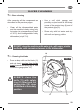
Fig. 3
EN
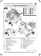
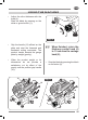
MAIN COMPONENTS
1.
Startup button
(white or green)
2. Stop button (black or red)
3. Machine running warning light
4. Slice thickness control knob
5. Adjustable foot
6. Carriage tray support
6a. Immovable cap nut
(x)
7. Base
8. Product tray
9. Blade plate
10. Product grip
11. Blade
12. Product grip handle
13. Manufacturer identification plate,
machine data and UE marks
14. Pusher plate extension
15. Product tray hand protection
16. Product tray handle
17. Blade plate tie-rod
18. Supply cord
19. Gauge plate
20. Sharpener
11
6
16
16
12
6a
17
7
18
4
4
14
8
8
19
19
5
5
5
15
15
9
10
20
13
1
2
3
21
S 220 AF
(x) (z)
F 250 E
(x) (z)
F 250 I
(x) (z)
F 275 E
(x) (z)
F 275 I
(x) (z)
F 275 IL
(x) (z)
F 300 R
(x) (z)
F 300 E
(x) (z)
F 300 EL
(x) (z)
F 300 CL
(x) (z)
F 300 I
(y)
F 330 I
(y)
F 350 I
(y)
F 370 I
(y)
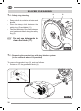
Fig. 4
(x)
(y) (z)
EN
MAIN COMPONENTS
1.
Startup button
(white or green)
2. Stop button (black or red)
3. Machine running warning light
4. Slice thickness control knob
5. Adjustable foot
6. Carriage tray support
6a. Immovable cap nut
(x)
6b. Knob
(y) (z)
7. Base
8. Product tray
9. Blade plate
10. Product grip
11. Blade
12. Product grip handle
13. Manufacturer identification plate,
machine data and UE marks
14. Pusher plate extension
15. Product tray hand protection
16. Product tray handle
17. Blade plate tie-rod
18. Supply cord
19. Gauge plate
20. Sharpener
(x) (y)
standard /
(z)
on request
11
6
16
16
12
6a
17
7
4
4
14
8
8
19
19
5
5
15
9
10
20
18
5
13
1
2
3
6
6b
15