Fastmark 4000 Series with PALTM Print and Program Language Barcode Label Printer User’s Guide Part No.
AMT Datasouth Corp. Corporate Headquarters 4765 Calle Quetzal Camarillo, CA 93012 (805) 388-5799 PH (805) 484-5282 FX Charlotte Operation 4216 Stuart Andrew Blvd. Charlotte, NC 28217 (704) 523-8500 PH (704) 525 6104 FX www.amtdatasouth.
IMPORTANT SAFETY INSTRUCTIONS AND OTHER NOTICES ! This label printer complies with the requirements in Part 15 of FCC rules for a Class A computing device. Operation of this equipment in a residential area may cause unacceptable interface to radio and TV reception, requiring the operator to take whatever steps are necessary to correct the interference. ! Place the printer on a flat, firm and solid surface. ! Do not place the printer near a heat source or near water.
TRADEMARK CREDITS Windows ® , MS-Word and MS-DOS are registered trademarks of Microsoft Corporation PC ® is a registered trademark of International Business Machines Centronics ® is a registered trademark of Centronics Corporation COPYRIGHT NOTICES © 2003 AMT Datasouth Corp. All rights reserved. © 2003 Adobe Systems Incorporated © 1996-2003 The FreeType Project. All rights reserved. © 1993 Symbol Technologies, Inc. © 1990 United Parcel Service of America, Inc.
CONVENTIONS Some of the procedures in this guide contain special notices that highlight important information: Note Indicate information that you should know to help your printer run properly and efficiently. Caution Indicate guidelines that, if not followed, can cause damage to equipment. Warning Indicate a situation where there may be a danger to you. Important Indicate that the associated material needs to be done to ensure proper printer operation.
Table of Contents TABLE OF FIGURES.......................................................................................................8 INTRODUCTION..............................................................................................................9 MODEL OVERVIEW.....................................................................................................10 Models..........................................................................................................................
Example of a Procedure defined in PALTM .................................................................. 54 Example of calling a Procedure from a host application ............................................. 54 Demo Label showing use of Print Utility Procedures .................................................. 55 Example of How to Define Label Formats .................................................................. 56 Example of calling Label Format from Host Application...............................
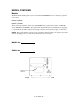
TABLE OF FIGURES Figure 1 – Model and Serial Number Location............................................................................. 10 Figure 2 – Traditional Printing...................................................................................................... 12 Figure 3 – Legacy Data stream Interpretation............................................................................... 13 Figure 4 – Stand Alone Operation...........................................................................
INTRODUCTION The FM4602 / FM4603 are high-performance, low-cost Direct Thermal/Thermal Transfer labeling printers featuring the PALTM Print and Program language. PALTM Print and Program language is an interpretive page description language that allows printers to move beyond the role of normal printers. In addition to supporting traditional text, bar code, and graphics print sequences common to other printers, PALTM Print and Program language also serves as a general purpose programming language.
MODEL OVERVIEW Models The PALTM Print and Program versions of the Fastmark FM4000 series are currently comprised of 2 models: FM4602 (200DPI) FM4603 (300 DPI) These models are similar in many ways. The FM4602 has a print head resolution of 200 DPI versus 300 DPI on the FM4603. Throughout this manual instructions and illustrations applying to a particular model will be labeled accordingly otherwise the instructions apply to all models.
Model Features For detailed feature specifications, please refer to Appendix A. Below is a brief summary of printer features: Standard Features PALTM Print and Program Language. The PALTM Print and Programming Language is a powerful printer language combining both exceptional printing abilities with flexible programming abilities.
PALTM PRINT AND PROGRAM OVERVIEW Printers featuring PALTM Print and Program ability can be used in several ways in any given environment. This section describes 3 common ways this advanced capability is used. Details of how to take advantage of this advanced ability can be found in the PALTM Print and Program Reference Manual. For help and assistance determining the best way to use this ability in your situation, please consult your sales representative.
Legacy Data Stream Interpretation PALTM Print and Program capable printers uniquely address applications where upgrading to modern cost effective technology is desired. Often cost-prohibitive software reprogramming to change a data stream prevents an organization from moving to new printing technologies. Using a PALTM Print and Program capable printer solves this problem. In this case a PALTM program is written which interprets a data stream normally sent to the legacy device being replaced.
Standalone/Downtime Applications PALTM Print and Program capable printers may be programmed to operate independent of a PC/host connection. This standalone ability may be used in cases where no PC/host connection is needed or as a fail-safe backup when the PC/host or network is unavailable. The Standalone Application program is stored in the printer memory and can accept input from a PS/2 keyboard, bar code scanner, or other serial devices such as an electronic scale.
UNPACKING AND INSPECTION This section is provided to assist you in taking the printer from the shipping container to the application environment and ready for use. 1. Remove top foam packing piece. 2. Lift printer straight up out of box carefully with adequate assistance. 3. Remove accessory kit and supplies. 4. Remove printer from plastic bag. NOTE: Save box and all packing materials for future use, in the event the printer needs to be shipped.
INSTALLATION AND CONFIGURATION Setting up the Printer Before setting up the printer you should first consider the following: • Flat stable surface with sufficient clearance to allow for interface cables and media loading. • Free from excessive direct sunlight, temperature, humidity, dust, dirt, and debris. • Near a grounded AC power receptacle wired in compliance with local ordinances. Media Viewing Window Back-Lit LCD FEED / CONFIG. PAUSE / CALIBR.
Connecting the Power Cord 1. Ensure printer Power Switch is off "0". 2. Connect the power cord to the AC Inlet Receptacle located on the back of the printer. 3. Connect AC power plug to a suitable AC source. 4. Connect either Centronics Parallel cable or RS-232 Cable.
Connecting the Printer to Your Host 1. You can connect the printer with any standard Centronics cable to the parallel port of the host computer or network print server. 2. Or, you can connect the printer with a serial cable to the RS-232C port of your computer or terminal. (For PC compatibles, the RS-232C port is COM1, COM2 or COM3.) NOTE: Using Centronics allows for higher communication speed than serial. Figure 9 - Communication Cable 3.
Loading the Ribbon Thermal Transfer Media only If Direct Thermal Media is used, skip to the section Loading Media. 1. Open the Media Access Cover by lifting it up until it rests upon the top of the printer. 2. Open the Front Access Door by rotating it down. Media Access Cover Media Supply Guide Media Supply Spindle Front Access Door Figure 10 - Open Media Access Cover 3. Rotate the Green Print head latch counter-clockwise to open the print head module. 4.
5. Unwrap the ribbon and place the Ribbon Supply Roll on the Ribbon Supply Spindle located towards back of printer. Take-up Spindle Supply Roll and Supply Spindle Empty Take-up core Figure 12 - Ribbon Take-Up Core 6. Place the Ribbon Take-up core on the Ribbon Take-Up Spindle located towards the front of the printer. 7. Slide both cores completely towards the center of the printer. 8. Route the ribbon under the print mechanism. 9.
11. Important: To ensure proper ribbon operation complete the following checklist: # # Ribbon is wound ink in and feeding off the top of the Ribbon Supply Roll. # Ribbon is re-wound on Take Up Roll from the bottom. # Ribbon is routed above the Upper Media Sensor Arm. Only the media should be below this arm. # When properly loaded both the Ribbon Supply and Ribbon Take-Up Rolls will be rotating counterclockwise as shown on the Ribbon Routing picture.
3. Rotate the green Print head Latch counterclockwise to open the print head. 4. Rotate the Side Access Door down to allow the media to be loaded under the print head module. Print head Latch Upper Media Sensor Arm Lower Media Sensor Arm Side Access Door Figure 15 - Print head Latch and Side Access Cover 5. Slide the Media Supply Guide to the full widest position. 6. Ensure the media is face out with the labels feeding from the top of the roll. If not obtain correctly wound media from your supplier 7.
11. Thread the media over the Back Media Rail and under the Front Media Rail. 12. Continue feeding the media through the black Upper and Lower Media Sensor Arms located under the print module. 13. Place the green Outside Media Guide (smooth side in) back onto the Front and Back Media Rails. 14. Slide the Outside Media Guide towards the center of the printer until it just touches but does not buckle the media. 15.
Upper Media Sensor Arm Media Back Media Rail Front Media Rail Lower Media Sensor Arm Figure 18 - Media Routing 17. Rotate the Side Access Door up to close. 18. Rotate the green Print Head Latch clockwise fully to lock the print head and Side Access Door shut.
Changing Position of the Media Supply Spindle The printer can store under the Media Access Cover an 8-inch outer diameter media roll that is wound on either 1.5 inch or 3 inch inner cores. When the Media Access Cover is closed touching on either the Media Cover or the bottom of the printer could cause unnecessary drag on the form. The printer's Media Supply Spindle can be moved to accommodate these issues. To change the position of the Media Spindle: 1. Turn off the printer. 2.
Calibrating Media Sensors Important: The first time media is installed, the Media Sensors must be calibrated. After the first calibration no further calibration is required unless the media type (length, color, backing material, etc.) is changed or irregular feeding occurs. 1. Ensure the printer is powered off. 2. Verify that the media is properly loaded and routed as detailed in Loading Media Section. 3.
Printing the Configuration Label 1. Power off the printer. 2. Make sure that 4 inch wide media is installed. The Self-test will print the maximum width of the installed label. 3. Press and hold the FEED/Config button. 4. Power on the printer. 5. Release the FEED/Config button when the media begins to feed. NOTE: The following figure is an example configuration printout. The feature setting on your printer may vary based on any setup changes made or firmware version installed in the printer.
KEYPAD OPERATION Figure 21 - Fastmark 4000 Series Front Panel LED Description LED Function ❍ READY ON: Printer is online OFF: Printer is either off line or in setup mode Steady Blinking: System error occurred. (See LCD for description of error and refer to Trouble Shooting Section) Flickering: Printer is receiving data from serial or parallel interface ❍ MEDIA OFF: No media errors detected Steady Blinking: Media error occurred.
Key Operation The Front Panel keys serve multiple functions. Refer to the following tables for their specific functions. Power up key functions The table below indicates the function performed when a key is pressed and held while the printer is powered up. Key FEED PAUSE CANCEL Function The printer generates a configuration label showing current feature settings, firmware revision, and PALTM drive storage capacity.
On Line key functions On Line: PAL Emulation Key Function FEED No function. PAUSE Places the printer Off Line. CANCEL No function Off Line key functions Off Line: PAL Emulation Enter Setup Mode Key Function FEED Feeds one label. PAUSE Places the printer On Line. FEED + PAUSE Pressing FEED and PAUSE simultaneously places the printer in Setup Mode. Pressing FEED and CANCEL simultaneously also places the printer in Setup Mode.
Setup Key Functions while in Changing Feature Mode Media Type: Thermal Transfer Feature Feature (LCD Top Line Not Blinking) Key FEED + PAUSE FEED + CANCEL PAUSE CANCEL Function While holding the FEED key, each press of the PAUSE key scrolls up through the list of features by one feature. Holding the PAUSE key scrolls up through the feature list. This list wraps from the first feature to the last feature in the list. See the Setup Menu section for more information.
Setup Key Functions while in Changing Value Mode Media Type: Thermal Transfer Value Value (LCD Top Line Blinking) Button FEED + PAUSE FEED + CANCEL CANCEL Function While holding the FEED key, each press of the PAUSE key increases the value or scrolls up through the list of values. Holding the PAUSE key continuously scrolls though the available feature values. This list wraps from the upper limit to the lower limit of the particular feature being adjusted.
LCD Display The front panel is equipped with a 2 row by 16 character back-lit Liquid Crystal Display (LCD). The basic function of the display is to: # Display the printer line status # Display error conditions # Display the name and state of a PALTM program loaded and running on the printer. # Display setup features and values. # Display data prompts requesting data from an attached keyboard or bar code reader. These prompts vary depending on the individual PALTM program loaded on the printer.
TM Typical Display with a PAL program loaded If a PALTM program is loaded on the printer, the message displayed on the LCD will vary depending on the application but may be similar to the following: General Hospital Waiting for Data With stand-alone PALTM application loaded If a PALTM program is loaded on the printer which operates in stand-alone mode (no connection to host or PC), the message displayed on the keypad will vary depending on the application but may be similar to the following: Enter Patie
Setup Menu Operation The standard feature settings are stored in non-volatile memory. These settings are detected and applied at power up. After power up, any changes made to the standard feature settings will take effect immediately. At power down the current standard feature settings are saved to nonvolatile memory. Any feature values modified by PALTM sequences are also retained on power down unless the keypad is locked. Setup Example 1) Press PAUSE to place printer Off Line.
Setup Feature and Value List FEATURE NAME VALUE RANGE DESCRIPTION Media Type [ Direct Thermal, Thermal Transfer ] Set to Thermal Transfer if ribbon is used. Media Sensing [Gap, Continuous, Black Bar ] Set to match media sensing method. Calibrate Media (Form Length / Gap Length) automatically displayed and are not adjustable from this feature. Pressing CANCEL initiates the media calibration. The detected media length and Gap are displayed.
Setup Feature and Value List (continued) Vert Print Align [ -0.50 - +0.50 ] (Inches) Adjust to move printed image up or down on label. Positive values move image up. Negative values move image down. Horz Print Align [ 0.00 - 1.00 ] (Inches) Adjust to move printed image left or right. Larger values move the image to the right. Vert Size Adjust [ -60 - + 60 ] Vertically expands or compresses print image. Negative values are compressed, positive values are expanded.
Setup Feature and Value List (continued) Emulation Mode [ PAL, ASCII, Hex, Display ] Selects active emulation. ASCII emulation is a basic text emulation. Hex and Display emulation's are used for printing data in a format which shows the exact data being received by the printer. This is useful trouble shooting communications or host programming issues. Date [MM/DD/YYYY] If RTC option is installed, this feature allows the date to be set. Press the Cancel key to select Month/Date/Year to modify.
PS/2 Keyboard Interface A PS/2 keyboard interface is standard on the FM4602 and FM4603. This allows keyboard input or PALTM programs running on the printer. Typically a PALTM program is written to write prompts to the printer LCD requesting data from the user. This data can then be entered on the keyboard. The use of a keyboard wedge cable also allows the use of a bar code scanner.
PALTM PRINT LANGUAGE INTRODUCTION This section provides an introduction to basic PALTM print language abilities including fonts and bar codes. For information regarding PALTM programming abilities, creating stand-alone applications, and other advanced topics please refer to the Fastmark PALTM Print and Program Reference Manual. The Windows driver included with the printer is an excellent method to generate PALTM print sequence based commands.
Smooth Scalable Fonts PALTM Print and Program capable printers allow a font to be selected by name, scaled, rotated, and placed on the drawing service. The table below lists the unique names used to select the fonts and a print sample for each showing the point size. Please refer to the PALTM Print and Program Reference manual for detailed information on the use of fonts. Font Point Size PALTM Identifier Sans Serif 6 Sans6.00pt Sans Serif 8 Sans8.00pt Sans Serif 10 Sans10.
Supported Bar Codes PALTM Print and Program capable printers allow a bar code to be selected by name, rotated if needed, and placed on the drawing service. All popular linear and 2D bar codes are supported. Depending on bar code type, a number of parameters may be adjusted as needed for example human readable, height, X dimension, check digits. Please refer to the PALTM Print and Program Reference manual for detail information on the use of bar codes.
Codabar /Codabar Postnet /Postnet Maxicode /Maxicode MSI Plessy /MSI PDF-417 /PDF417 Table 2 – PAL Bar Code List and Samples User's Guide 43
PALTM Print and Program Label Tutorial This Label Tutorial provides instructional steps showing the basic commands needed to create labels using PALTM Print and Programming Language. This section covers some of the most common sequences used to print fonts, bar codes, lines etc. Each label introduces a basic concept and builds on the preceding label. Upon completion of the tutorial, a label consisting of text in two orientations, a line, a box and a bar code will be covered.
Printing Text on a Label PALTM Command Sequences Label Output Hello World! /Sans12.00pt findfont 12 scalefont setfont 72 72 moveto (Hello World!) show 1 _showpages 1" 1" Purpose: Demonstrate how to print simple text on a label. findfont - Establish the font to use The fontname is preceded by a “/”. In this example, a Sans Serif 12 point font was chosen. See Table 1 for supported fonts. scalefont – Scale the selected font’s size in points It is typical to use the value indicated in the selected font.
PALTM Print and Program Coordinate System The default coordinate system used by PALTM Print and Program Language is a traditional Cartesian coordinate system with the origin at the lower left-hand corner of the drawing surface: y (0,0) x PAL Coordinate System An internal “cursor” is maintained by PALTM that keeps track of where to put the next print object, i.e. text or lines, etc. At power up this internal cursor is set to the origin or (0,0).
Printing a Line PALTM Command Sequences Label Output /Sans12.00pt findfont 12 scalefont setfont 72 72 moveto (Hello World!) show 72 68 moveto 144 68 lineto stroke 1 _showpages Hello World! 1" 1" Purpose: Demonstrate drawing lines on a label. This example underlines the “Hello World!” text from the previous example.
Printing a Box PALTM Command Sequences Label Output /Sans12.00pt findfont 12 scalefont setfont 72 72 moveto (Hello World!) show 72 68 moveto 144 68 lineto 30 30 moveto 258 30 lineto 258 258 lineto 30 258 lineto closepath 2 setlinewidth stroke 1 _showpages Hello World! 1" 1" Purpose: Demonstrate the drawing of a rectangular box. This example builds on the previous example by drawing a frame around the label. A 4” x 4” (288 points x 288 points) label is used in this example.
Rotate a Text Object PALTM Command Sequences Hello World! Label Output Hello World! 1" 1" /Sans12.00pt findfont 12 scalefont setfont 72 72 moveto (Hello World!) show 72 68 moveto 144 68 lineto 30 30 moveto 258 30 lineto 258 258 lineto 30 258 lineto closepath stroke 72 90 moveto 90 rotate (Hello World!) show -90 rotate 1 _showpages Purpose: Demonstrate how to rotate text. This example builds on the previous example by placing another instance of “Hello World!” rotated 90 degrees.
Printing a Bar Code PALTM Command Sequence Hello World! Label Output /Sans12.00pt findfont 12 scalefont setfont 72 72 moveto (Hello World!) show 72 68 moveto 144 68 lineto 30 30 moveto 258 30 lineto 258 258 lineto 30 258 lineto closepath stroke 72 90 moveto 90 rotate (Hello World!) show -90 rotate 100 100 moveto (BARCODE123) /Code39 _barcode 1 _showpages *BARCODE123* Hello World! 1" 1" Purpose: Demonstrate how to print a bar code.
INTRODUCTION TO PALTM ADVANCED TOPICS Advanced Overview As previously mentioned the PALTM Print and Program Language is both a powerful printing and programming language. For example the included Windows driver takes advantage of the powerful printing portion of the language. Your VAR or internal programming staff may take advantage of some of the programming abilities. The fact that a single printer language supports both capabilities is unique.
PALTM Print and Program Language Features # Page Description Language # No control Codes (easy to pass through networks, filters, etc.) # Compatible with midrange and mainframe computers and any host or PC programming language.
Sample Demo Files Several text files containing PALTM examples are included on the product CD. These files show programming techniques and examples, which may be incorporated into host or PC programming or just used as reference. Each text file includes descriptive comments within the file. Below is a description of each file: File Name Description Pal_Procs_and_Formats.txt This file contains a number of print utilities written as PAL procedures.
Example of a Procedure defined in PALTM The following procedure is defined in Pal_Procs_and_Formats.txt and illustrates how PAL commands may be combined in a procedure to create a completely new function or capability. The file Pal_Procs_and_Formats.txt must be copied to the printer prior to using any of these utilities. The following utility shows how PAL operators are used to create a simple Box draw procedure. This Box procedure makes use of another procedure defined called inchtopts.
Demo Label showing use of Print Utility Procedures After the file Pal_Procs_and_Formats.txt has been copied to the printer, a number of new procedures are now defined in the printer (until powered off). These procedures have been written specifically to demonstrate how to use the Pal Print and Program operators to produce printed output. These procedures also provide easy ways to print various objects without actually needing to know the PAL language.
Example of How to Define Label Formats The example below shows how a label format can be defined as a PAL procedure. This label format called Mailing_Label uses 5 variables. Notice how the variables are defined in reverse order compared to how this format is called. This format is defined in Pal_Procs_and_Formats.txt. Looking at this file will also reveal that this procedure makes use of the print utility procedures also defined in this file.
Example of calling Label Format from Host Application The example below shows how a form named Mailing_Label which was defined in the file Pal_Procs_and_Formats.txt may be called from a host or PC application. The file Pal_Procs_and_Formats.txt must be copied to the printer first before the label format is defined. Also it is possible to store the formats in Flash memory which is an advanced topic not covered here. Other examples of calling these formats may be found in Format_Demo.
WINDOWS PRINTER DRIVER Windows 2000 Driver Installation 1. From the task bar select Start->Settings->Printers. The printers folder should be displayed. 2. Double click the Add Printer icon. # The Add Printer Wizard dialog should be displayed. # Click the Next button. 3. Select the Local printer option and click the Next button. 4. Select the desired printer port and click the Next button. 5. From the Manufacturers list dialog click the Have Disk button. 6.
Windows XP Driver Installation 1. Go to the Printers and Faxes folder. 2. Double click the Add Printer icon. The Add Printer Wizard dialog should be displayed. Click the Next button. 3. Select the Local printer option and click the Next button. 4. Select the desired printer port and click the Next button. 5. From the Manufacturers list dialog click the Have Disk button. 6. From the Install From Disk dialog browse to the location of the driver files and click OK. 7.
Selecting Printer Fonts When the driver is installed, a custom True Type font is also installed called AMTDS Sans Serif which closely matches the resident scalable font in the printer. This font may be printed in a variety of point sizes. Using this font increases print speed and minimizes the data transmitted to the printer. Use of other True Type fonts are supported but are printed as graphics. To use the printer resident font: 1) For each size font highlight the font using the mouse.
Printing Bar Codes From Windows Applications Using the Fastmark PALTM Windows driver, printing bar codes from any Windows application is possible. These bar codes are printed using the internal bar code ability of the printer resulting in superior bar code quality. The following steps indicate how to do this: 1) Ensure the Fastmark PALTM Driver is selected within this application. 2) Select the media size to be used for this label.
Adjusting the Windows Driver Bar Codes Using the method just described, any Windows application can produce bar codes using the Fastmark drivers. Simply selecting the font as a bar code font does this. The driver also provides ways to finely adjust the bar code printed. For example, human readable text may be enabled or disabled. The X dimension may be adjusted. Depending on the bar code type other parameters may be adjusted for example enabling or disabling a check digit.
Using the Windows Driver To Produce PALTM Print Command Examples To use the Windows driver to produce a PALTM sample for use in host programming do the following: 1) Design the label as needed using suitable Windows application. 2) Where possible always use the printer resident font such as AMTDS Sans Serif. 3) Use bar code fonts for data fields to be printed as bar codes. Use the driver Advanced Properties dialog box to select various options for the bar codes to be printed.
TROUBLESHOOTING AND MAINTENANCE The following errors may be detected and displayed by the printer. In each case either the Ready, Media, or Ribbon LED will blink steady. Printer Detected Errors LCD ERROR MESSAGE DESCRIPTION RECOVERY Error: Power Fail The printer has detected +24VDC has dropped below a minimum acceptable level causing the printer to back up all settings to EEPROM. Turn printer off, wait 5 seconds and turn back on.
Error: Ribbon Out Reported when the printer detects the end of ribbon while printing or feeding media after the current label is complete. Open the print head, remove old ribbon cores, replace with new ribbon ensuring the routing is correct. Close print head and follow recovery procedures. If this is direct thermal application, change Media Type feature to Direct Thermal. Error: Image System Error reported by the imaging sub-system indicating a memory shortage or other graphics problem.
Error: Keyboard Overflow This error indicates the incoming keyboard buffer has overflowed. This can occur if the PALTM application running on the printer is not reading keyboard input. Press the CANCEL key to clear the error. If the error repeats cycle printer power. If it still repeats report the error to the programming staff which created the currently loaded application. Error: Keyboard Comm Indicates a communication error between the printer and attached PS/2.
User Detected Errors The following issues may be detected by the user but are not reported by the printer. Vertical streaks in the print This could indicate a dirty or faulty print head. Clean the print head first. Verify the media does not have excessive paper fibers or dust. Verify there are no nicks or burrs anywhere in the paper path such as a scratched rail. If no other source of streaks can be found replace the print head. Vertical gaps in the print This could indicate a dirty or faulty print head.
Preventive Maintenance Before performing preventive or any other maintenance be sure to turn off the printer power. Cleaning the Print head (TPH) 1. Turn off the printer, open the covers, Print head module and remove the ribbon. 2. Rub the print head with a piece of cotton, which has been moistened with alcohol. 3. Check for any traces of black coloring or adhesive on the cotton after cleaning. 4. Repeat if necessary until the cotton is clean after it is passed over the head.
Appendix A: GENERAL SPECIFICATIONS NOTE: The FM4402 does not support the PALTM Print and Program Language but is included here for reference only.
Appendix B: INTERFACE SPECIFICATIONS This appendix presents the interface specifications of I/O ports for the printer. These specifications include pin assignments, protocols and detailed information about how to properly interface your printer with your host or terminal. Serial The RS-232 connector on the printer side is a female, DB-9.
Connection with host: Host 25S (PC or compatible) Printer 9P Host 9S Printer 9P (PC or compatible) DTR 20 DSR 6 TX 2 RX 3 CTS 5 RTS 4 GND 7 1 DSR 6 DTR 2 RX 3 TX 7 RTS 8 CTR 5 GND DTR 4 DSR 6 TX 3 RX 2 CTS 8 RTS 7 GND 5 ……….. ……….. ……….. ……….. ……….. ……….. ……….. ……….. ……….. ……….. ……….. ……….. ……….. ……….. 1 DSR 6 DTR 2 RX 3 TX 7 RTS 8 CTS 5 GND Alternatively you can connect the 3 wires in the following way.
Parallel (Centronics) The parallel port is a standard 36-pin Centronics. Its pin assignments are listed as following.
Appendix C: ASCII TABLE The following table may be used to determine HEX values of ASCII characters. For example the character A is hex 41 commonly shown as 0x41H.
Appendix D: SELF TEST PRINT SAMPLE User's Guide 74
Appendix E: HIDDEN KEYPAD FEATURES Hidden Setup Feature and Value List To access the hidden list of features, select the Firmware Rev. feature then press the Cancel key twice. The hidden feature list is now enabled and may be selected by pressing and holding the FEED key then pressing the Cancel key to scroll into this list. FEATURE VALUES DESCRIPTION Ripple Pattern N/A Press the Cancel key to initiate a rolling ASCII ripple pattern.
Hidden Setup Feature and Value List (Continued) Keypad Lockout Label Count [Enabled, Disabled] When Keypad Lockout is Enabled, the value of features may be viewed but not changed. Also, any feature value which may be changed from downline using a PAL operator is also locked out from change. This feature may be used to keep users from modifying features or to override host changes if needed. N/A This feature displays the number of labels printed since the printer was manufactured.
Appendix F: UPDATING PRINTER FIRMWARE Occasionally there may be a need to update printer firmware either to enhance capabilities or correct issues. Updating firmware via the serial or parallel interface is possible only after activating the printers boot mode firmware. There are 2 ways to do this: 1) Selecting the F/W Update mode from the hidden menu. # Activate the hidden menu as described in Appendix E.
After boot mode firmware is activated, the LCD will show the following. Off line: F/W Update Mode The only possible actions at this point are to enter boot mode setup mode or cycle power to exit this mode (after setting DIP SW 7 OFF). This setup mode works like normal setup mode except the feature list is limited to specific features used during firmware updates. Press the FEED + PAUSE keys to enter boot mode setup mode.
match host if needed. COM1: Parity Change to match host if needed. COM1: Data Bits Change to match host if needed. COM1: Handshake Change to match host if needed. Firmware Rev. Displays revision of boot code currently loaded. The boot code can only be updated by changing Flash chips located on main board.