7200 ATB Printer User's Guide Part No. 111017 Rev.
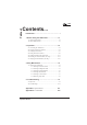
Table of 7200 Contents... Introduction.............................................................. i 1. Before Using the ATB Printer ......................... 1-1 1.1 Checking the Package ....................................................... 1-2 1.2 Names and Functions ........................................................ 1-3 2. Operation.......................................................... 2-1 2.1 Connecting the ATB Printer .............................................. 2-2 2.
7200 (Page is intentionally blank) Operation Manual
7200 INTRODUCTION NOTICE This equipment has been tested and found to comply with the limits for a Class A digital device, pursuant to Part 15 of the FCC Rules. These limits are designed to provide reasonable protection against harmful interference when the equipment is operated in a commercial environment. This equipment generates, uses and can radiate radio frequency energy and, if not installed and used in accordance with the instruction manual, may cause harmful interference to radio communications.
7200 Product Safety This manual uses a variety of terms and symbols to ensure the safe operation of the product, help prevent hazards to yourself and others, and help prevent property damage. The following describes terms, symbols, and meanings used in this manual. Before reading this manual, please familiarize yourself with the terms and symbols below. Terms WARNING Ignoring this cautionary note and handling the product improperly may result in death or serious injury.
7200 INTRODUCTION Safety Considerations READ THIS PAGE BEFORE INSTALLING OR USING THIS PRODUCT! WARNING n Do not remove the cover or attempt any repairs on this product. There is risk of electric shock. n Do not place heavy materials on the power cable. Do not bend or twist the power cable. The cable may get damaged, causing fire or electric shock. n Do not use damaged cables or broken connector or power plugs. There is risk of fire or electric shock.
200 Caution Label This product comes with a caution label attached as described below. Caution Label CAUTION Falling covers may cause injury. Do not take your hands off covers when opening and/ or closing them. Operating Environment Location • Do not place the product in direct sunlight or near heating sources such as stoves or heaters. • Do not place the product in a dusty or humid environment. • Do not place the product under strong shock or vibration.
7200 INTRODUCTION Back 9.8 in (250mm) Right Front 8.3 in (210mm) 9.8 in (250mm) 9.8 in (250mm) 9.8 in (250mm) Top Right Left 9.8 in (250mm) 8.3 in (210mm) 15 in (380mm) Left 21.6 in (550mm) 5.9 in (150mm) Space Required 9.
7200 Dimensions and Weight • 8.3 inches (210mm) W x 21.6 inches (550mm) D x 15.0 inches (380mm) H • Less than 35.3 lb. (16 kg ) Temperature and Humidity Make sure that the following temperature and humidity conditions are met : • Ambient temperature: 41 to 104 degrees F (5 to 40 degrees C) • Ambient humidity: 20% to 90% RH (relative humidity) — no condensation.
7200 INTRODUCTION Available Types The Sigma Data — 7200 ATB printer is classified into 2 types, i.e., Type B and Type D. Refer to the printer types listed below when reading this manual. Type Printing Method Number of Bins Type B Direct thermal only Two internal bins and one external bin (BIN 3) Type D Direct thermal or thermal transfer Two internal bins and one external bin (BIN 3) Note: Type B cannot be used for Thermal Transfer printing with a transfer ribbon.
7200 NOTES viii (page is intentionally blank) Operation Manual
7200 BEFORE USING THE S7200 1.
7200 1.1 Checking the Package The ATB printer and accessories are packed in the same box. Carefully remove the printer and accessories from the box and packing materials, then check that the package contains all of the items needed for operation that are pictured below. The package also contains a warranty card and may have other information sheets.
7200 BEFORE USING THE S7200 1.2 Names and Functions This section explains the names and functions of each part. 1.2.
7200 1.2.2 Functions 1-4 No. Names Functions A Operator panel Houses the LEDs and keypad needed to operate the ATB printer. B Cover lock Locks the side cover. (Use the key to open the cover.) C Inserter Used to insert single coupons (one at a time). D Output stacker Receives ejected coupons, print-side up. (Has a capacity of 100 coupons.) E Feed knobs Used to remove jammed coupons. F BIN 1, BIN 2, and BIN 3 load knobs Used to load coupons into the feed rollers for each bin.
7200 BEFORE USING THE S7200 1.2.3 Operator Panel Operator Panel Layout ONLINE ERROR DATA MODE LEDs LCD 16 columns by 2 rows ONLINE ENTER RESET QUIT EJECT TEST SET UP CLEANING ç è ê é Keys LED Functions LEDs indicate printer status by turning on, turning off, or blinking. ONLINE ON — The ATB printer is online. The ATB printer can receive and print data from the terminal. The printer is set online when the power is turned on. OFF — The ATB printer is offline (i.e.
7200 Key Functions Each key has two different functions for different operating modes. Function indicated at the top Enabled in ONLINE or OFFLINE mode. Function indicated at the bottom Enabled in TEST, SETUP, or CLEANING modes. Functions ONLINE ENTER key ONLINE Cycles the ATB printer between ONLINE (ticketing enable) and OFFLINE (local) mode. If the ATB printer is online, pressing this switch sets it offline. If the ATB printer is offline, pressing this switch sets it online.
7200 BEFORE USING THE S7200 TEST ç key TEST In OFFLINE (local) mode, pressing this key sets the ATB printer to TEST mode (maintenance mode). ç Pressing this key moves the cursor on the LCD panel to the left. Automatic repeat when held down. SET UP è key SET UP In OFFLINE (local) mode, pressing this key sets the ATB printer to SETUP mode (maintenance mode). è Pressing this key moves the cursor on the LCD panel to the right. Automatic repeat when held down.
7200 NOTES 1-8 (page is intentionally blank) Operation Manual
7200 OPERATION 2.
7200 2.1 Connecting the ATB Printer This section explains how to connect the ATB printer to the power supply and the terminal. 2.1.1 Connecting to a Wall Receptacle A. Check that the power switch on the ATB printer is turned off. B. Plug the power cable into the ATB printer. Then, plug the other end of the power cable into a wall receptacle. Ferrite Core Note! Only use the supplied power cable. Ensure that the power cord complies with all local ordinances. IMPORTANT...
7200 OPERATION 2.1.2 Connecting the Terminal Before connecting the printer to a terminal, do the following: A. Ensure that both the ATB printer and the terminal are turned off. B. Attach the communications cable to the RS-232 port located on the back of the ATB printer, labeled “HOST.” Then connect the cable to the terminal.
7200 2.2 Turning the Power On and Off After the ATB printer has been successfully installed and connected, turn on the power. Note! Turn on the terminal before turning on the ATB printer. Reverse the sequence when turning off the power. Turn the power switch on. The LCD panel displays the following three indicators in turn for specified intervals (a few seconds). Then, the ATB printer is set online. When the power is turned on, the four LEDs are turned on as part of the self test routine.
7200 OPERATION 2.3 Loading the Documents Documents are loaded into the bins. The printer has two internal bins (1 and 2) and one external bin (3). The two or three bins can store the same or different types of documents. When different types of documents are loaded, the bins are selected as specified by the terminal. 2.3.1 Loading Documents into BINs 1 and 2 Each internal bin can store up to 500 documents. The following explains how to load the documents.
7200 Side cover (top right) D. Slowly open the second side cover (top right) as wide as possible. E. Load the documents into the bin, with the magstripe facing up and the front end on the right. Load the box in the same manner, with the magstripe facing up and the front end on the right. There are two bins (BIN 1 and 2). Each bin can store up to 500 documents.
7200 OPERATION BIN 1 F. Hold the first document and insert it into the slot along the coupon travel guides until it stops. BIN 2 BIN 1 Visual inspection window G. Feed the document into the rollers. Turn the knob to feed the front end of the document until you hear a beep (if the printer is turned on). If the printer is off, turn the knob a full turn. For BIN 1: Turn the red knob, labeled 1, counter-clockwise as shown on the label.
7200 H. Close the side cover (top right). I. Set the key to the OPEN position, and close the side cover (bottom right). J. Lock the side cover by gently pushing the side cover and turning the key counter-clockwise to the LOCK position. Remove the key. Note! Be careful not to leave the key in the ATB printer. If the key cannot be removed in the LOCK position, turn it slightly clockwise or counter-clockwise.
7200 OPERATION 2.4 Setting Documents in BIN 3 You will need some space in the back side of the ATB printer to use BIN 3. Keep the documents in the box. Keep space for the documents. Documents Set the documents as follows: A. Open the box of documents and set it in the back of the ATB printer. Front end (Documents in a box) Note! Do not remove the documents from the box. Printer B. Set the documents as shown in the left figure.
7200 C. Release the key lock for the side cover. Turn the key clockwise to the OPEN position. Note! The key cannot be removed in the OPEN position. Falling covers may cause injury. Do not take your CAUTION hands off covers when opening and/ or closing them. D. Slowly open the first side cover (bottom right) as wide as possible. Side cover (bottom right) Side cover (top right) 2-10 E. Slowly open the second side cover (top right) as wide as possible.
7200 OPERATION Magstripe face down F. Insert the first document in the BIN 3 slot until it touches the feeding roller. BIN 3 slot G. Feed the document. Turn the green knob, labeled 3, counter-clockwise to feed the front end of the document until you hear a beep (if the printer is turned on). If the printer is off, turn the knob a full turn. Visual inspection window Note! Make sure that the documents do not touch each other in the visual inspection window. H. Close the side cover (top right).
7200 I. Set the key to the OPEN position, and close the side cover (bottom right). J. Lock the side cover by gently pushing the side cover and turning the key counter-clockwise to the LOCK position. Remove the key. Note! Be careful not to leave the key in the ATB printer. If the key cannot be removed in the LOCK position, turn it slightly clockwise or counter-clockwise.
7200 OPERATION 2.5 Loading Documents into the Inserter While the ATB printer is on, you can use the inserter to read and/or print a document. Note that only one document can be inserted at one time. With the printer turned on, insert a document into the inserter slot until you hear a beep. The ATB printer then draws the document in for printing. Note! Insert only one document at a time. Do not insert the next document before the previous document is ejected. Otherwise, a double-feed or paper jam occurs.
7200 2.6 Installing the Transfer Ribbon (TT — Type D Only) Install the transfer ribbon according to the procedure below. The following operation is only used for thermal transfer. Transfer ribbon A.1 Take the transfer ribbon out of the bag and remove the protector. Protector Ribbon loader Transfer ribbon Guide Transfer ribbon Ribbon loader B. Install the new ribbon on the ribbon loader: a) Place the full roll of ribbon on the right side of the loader.
7200 OPERATION D. Slowly open the first side cover (bottom right) as wide as possible. Falling covers may cause injury. Do not take your CAUTION hands off covers when opening and/ or closing them. Side cover (bottom right) Side cover (top right) Pivots E. Slowly open the second side cover (top right) as wide as possible. F. Install the transfer ribbon. Gently push the transfer ribbon into the receptacle until both pivots click and hold the ribbon.
7200 G. Remove the ribbon loader. Squeeze the lock with your fingers to remove the loader. Lock Note! Make certain that both ribbon cores are clicked on the pivots. Transfer ribbon winding direction H. Turn the ribbon take-up core in the direction of the arrow until the ink portion of the transfer ribbon is seen. Then, turn it at least 3 additional times. Note! Be careful of which direction you turn the ribbon core. Only turn the core in the direction indicated by the arrow! I.
7200 OPERATION J. Set the key to the OPEN position and close the side cover (bottom right). K. Lock the side cover by gently pushing the side cover and turning the key counter-clockwise to the LOCK position. Remove the key. Note! Be careful not to leave the key in the printer. If the key cannot be removed in the LOCK position, turn it slightly clockwise or counter-clockwise.
7200 2.7 Changing Transfer Ribbons (TT — Type D Only) When the transfer ribbon needs replacement, the LCD panel displays a message. LCD Panel Display The following operation is only for thermal transfer. WARNING: END OF RIBBON Replace the transfer ribbon following the steps below: A. Release the key lock of the side cover. Turn the key clockwise to the OPEN position. Note! The key cannot be removed in the OPEN position. B. Slowly open the first side cover (bottom right) as wide as possible.
7200 OPERATION D. Pinch both blue pivots to unlock and take out the used transfer ribbon. Note! It is normal for some unused transfer ribbon to be on the ribbon core. Pivots E. Refer to the section, “Installing the Transfer Ribbon,” to install a new ribbon. Treat used transfer ribbons as plastic waste.
7200 NOTES 2-20 (page is intentionally blank) Operation Manual
7200 DAILY MAINTENANCE 3.
7200 3.1 Cleaning the ATB Printer This section explains the ATB printer components that need regular cleaning. Notes on Cleaning: Turn the power off and unplug the power cable before starting any cleaning procedure except when using the cleaning card! Only use water or neutral detergents, or isopropyl alcohol as specified. Never use harsh cleaning chemicals! 3.1.1 Cleaning the Printer Surface Use a cloth moistened with water or a neutral detergent to wipe the ATB printer surface.
7200 DAILY MAINTENANCE 3.1.2 Cleaning the Magnetic Head Magnetic particles, paper particles, or dust sticking to the magnetic head may cause read errors. Before starting the day's transactions, use the cleaning card to clean the magnetic head. The cleaning card is optional (sold separately). The following explains how to clean the magnetic head. A. Turn on the ATB printer. Press the ONLINE key to set the ATB printer offline (local mode). ONLINE ENTER B. Press the CLEANING key.
7200 C. Insert the cleaning card. • Insert the cleaning card with the instruction label on the card facing upward. • The LCD panel displays "Maghead Cleaning." while the ATB printer cleans the magnetic head. • At the end of cleaning, the cleaning card is automatically ejected into the output stacker. Output stacker Cleaning card Repeat the cleaning procedure several times as necessary.
7200 DAILY MAINTENANCE 3.1.3 Cleaning the Thermal Head Clean the thermal head when replenishing a bin with documents or when changing the transfer ribbon. Use a cotton swab moistened with isopropyl alcohol. Do not use thinner or benzene. Note! Be careful not to injure your hands when cleaning the thermal head. Using thinner or benzene to clean the thermal head will damage the head and may void your warranty. A dirty thermal head lowers printing clarity.
7200 3.1.4 Cleaning a Platen Roller Clean the platen roller when replenishing a bin with documents. Use a cotton swab moistened with isopropyl alcohol. Do not use thinner or benzene. Note! Be careful not to injure your hands if you clean the platen roller yourself. Using thinner or benzene to clean the platen roller will damage the roller. A dirty platen roller lowers printing clarity. The following explains how to clean the platen roller. Before cleaning the platen roller, remove the transfer ribbon.
7200 DAILY MAINTENANCE 3.1.5 Cleaning a Carrier Roller Paper dust and other dirt clinging to a carrier roller can cause a paper jam or poor printing (ex. data can be printed at a slant on the paper). The procedure for cleaning the carrier roller is explained as illustrated below. The carrier roller should be cleaned while the side cover remains open.
7200 Bin and Cutter Blocks Upper knob — for cleaning stock bin roller Lower knob — for cleaning cutter block roller Head position of the cleaning sheet The stock bin and burster rollers should be cleaned every 5000 documents or if printer performance degrades. The long, thin cleaning sheet is used for cleaning rollers, (not the card with the printed label which is used to clean the magnetic heads). Avoid fire when using isopropyl CAUTION alcohol to avoid the risk of burning. 3-8 1.
7200 DAILY MAINTENANCE 3.1.6 Removing Paper Dust Paper dust should be removed from the dust tray periodically. A. Pull out the knob, take out the dust tray, and remove paper dust from the dust tray. Dust tray Knob B. Return the dust tray to the original position. Firmly push the knob into the recess and insert the dust tray. C. Using a can of compressed air, thoroughly blow dust out of the document path.
7200 NOTES 3-10 (page is intentionally blank) Operation Manual
7200 TROUBLESHOOTING 4.
7200 9.1 Paper Jam In the event of a coupon jam, a buzzer sounds and the LCD panel displays a message indicating the location of the jam. 4.1.1 Part Names Bin block Inserter block Printing block and output stacker Cutter block Magnetic block 4.1.2 Jam Locations and Corresponding Messages PAPER JAM:ZONE C PAPER JAM:ZONE A PRINTING BLOCK STOCKER __ Paper jam in BIN 2 Either of 1, 2, or 3 is displayed on the LCD panel shown above.
7200 TROUBLESHOOTING 4.1.3 Removing the jammed coupon To remove the jammed coupon, check the location of the jam and follow the steps below. Jam Position Removing Procedures Stocker (Bin) block A, B, C‚ H, I, J Cutter block A, B, D, H, I, J Magnetic block A, E, I, J Printing block Output stacker A, F, I, J Inserter A, G, I, J • In the table above, Steps A through J correspond to the step numbers in the following procedures. Unlock the cover before starting any procedure.
7200 A. Slowly open the first side cover (bottom right) as wide as you can. Falling covers may cause injury. Do not take your CAUTION hands off covers when opening and/ or closing them. B. Slowly open the second side cover (top right) as wide as you can. Falling covers may cause injury. Do not take your CAUTION hands off covers when opening and/ or closing them. For a jam in BIN 1 C. Remove the jammed coupon from the appropriate bin. 1.
7200 TROUBLESHOOTING 2. Turn the knob to return the jammed coupon to the bin area. 3. Pull the jammed coupon out and remove it. D. Remove the jammed coupon (cutter block) After the jammed coupon has been cut: 1. Locate the blue knob labeled "Forward.
7200 2. Turn the feed knob to feed the jammed coupon to the magnetic block. (Go to Step E to remove the jammed coupon.) Feed knob If the jammed coupon has NOT been cut: 1. Use the knob for the appropriate bin AND the feed knob. 2. Turn both knobs clockwise simultaneously to return the jammed coupon to the input slot.
7200 TROUBLESHOOTING 3. Pull the jammed coupon out of the input slot and remove the damaged coupon. E. Remove the jammed coupon from the magnetic block. 1. Insert your fingers into the hole on the guide face, then lift and remove the jammed coupon while rotating the feed knob back and forth. Side pressure roller Operation Manual 2. Take out the jammed document while pulling down the side pressure roller. (The document is lifted up when the side pressure roller is pulled down.
7200 F. Remove the jammed coupon from the printing block and output stacker. The method varies depending on the location of the jammed coupon. When the jammed coupon is caught by the rollers shaded in the figure to the right: Printing block and output stacker block 1. Locate the blue feed knob for the output stacker. Feed knob 2. Turn the feed knob in the direction of the arrow to feed the jammed coupon to the output stacker.
7200 TROUBLESHOOTING When the jammed coupon is not caught by the rollers shaded in the figure: 1. Locate the blue feed knob labeled "Forward." Feed knob 2. Turn the knob in the direction of the arrow to feed the jammed coupon to the magnetic block. To remove the jammed coupon, go to step E.
7200 G. Remove the jammed coupon. (Inserter) When the jammed coupon is in the shaded portion of the figure to the right: Inserter Blade (The rear end of the jammed ticket is on the blade.) 1. Locate the blue feed knob labeled "Forward." Feed knob 2. Turn the feed knob in the direction of the arrow to feed the jammed coupon to the inserter.
7200 TROUBLESHOOTING H. Close the side cover (top right). CAUTION Falling covers may cause injury. Do not take your hands off covers when opening and/ or closing them. I. Set the key to the OPEN position, and close the side cover (bottom right). J. Lock the side cover by gently pushing the side cover and turning the key counter-clockwise to the LOCK position. Remove the key. Note! Be careful not to leave the key in the printer.
7200 4.2 Error Messages When an error has occurred in the ATB printer, an error message is displayed on the LCD panel. The error messages are listed in the table below. Error Message Error State Recovery Procedure WARNING: Indicates a relatively minor error, ex. when consumption articles (documents, etc.) has run short (paper-out), when the operator has made a mistake, etc. Open the cover, take necessary actions for recovery, and close the cover. If the error continues, contact a service technician.
7200 TROUBLESHOOTING Error Message Error State Recovery Procedure OUT OF REQUESTED PAPER The requested document has ended. Install the documents. ENCODING ERROR REMOVE VOID DOC. Encoding could not be executed normally. Remove the void coupon. MULTIPLE ENCODING ERROR Encoding error has occurred twice continuously. Remove the void coupon and clean the magnetic head. Verify that the coupon is properly inserted. CHECK-IN IN PROGRESS The interface has an error. (During the Check-In.
7200 The following error messages are reference data. They concern a service engineer. 4-14 Error Message Error State Recovery Procedure ILLOGICAL COMMAND The interface has an error. (An illogical command has been received.) Contact a service technician. INCORRECT FIELD The interface has an error. (An incorrect element has been received.) OUT OF SEQUENCE The interface has an error. (The sequence of the inserted document is incorrect.) NO PECTAB AVAILABLE The interface has an error.
7200 TROUBLESHOOTING Error Message Error State Recovery Procedure SYSTEM ERROR: PRINT POSITION An error has occurred during the print head positioning. Contact a service technician. SYSTEM ERROR: FUSE A fault was detected in the fuse. SYSTEM ERROR: SERVOMOTOR The servo motor is overloaded. COM.ERROR: PARITY The RS232C interface has an error. (An error was detected in the communication parity.) COM.ERROR: PROTOCOL = ** The RS232C interface has an error.
7200 NOTES 4-16 (page is intentionally blank) Operation Manual
7200 APPENDIX Appendix 1: Specifications A.1.
7200 A.1.2 Covers Open (swing down) the bottom right side cover first, then open (swing up) the top right side cover. You can insert the documents, change the ribbons (when TT is set), take out a jammed document, and perform cleaning and other tasks while the covers are open. The cover lock (key operated) is on the bottom right side cover. (See "Space Required.
7200 APPENDIX A.1.3 General Specifications and Power requirements Dimensions and Weight • • 8.3 inches (210mm) W x 21.6 inches (550mm) D x 15.0 inches (380mm) H Less than 35.3 lb. (16 kg ) Temperature and Humidity Make sure that the following temperature and humidity conditions are met : • Ambient temperature: 41 to 104 degrees F (5 to 40 degrees C) • Ambient humidity: 20% to 90% RH (relative humidity) — no condensation.
7200 A.1.4 Bins and Feeder This ATB printer has 2 internal bins and a third external bin as standard. Each of them can contain documents for printing. The specifications of each bin are as follows: (1) Bins Bin No. Standard Internal Capacity 1 ü ü 500 2 ü ü 500 3 ü (2) Document specifications (3) Detection (4) Documents set Document Types IATA Resolution 1720a, 1722c, 722c, 722d, 722e, Continuous-fanfolds 1000 Refer to the ATB Printer Document Specifications.
7200 APPENDIX A.1.7 Inserter (1) Document feeding direction (2) Shutter (3) Non-standard documents inserted (4) Document feeding (5) Documents rejected Face side up, leading side first in Not available Passed back to the front inserter to be kept, or jammed in the carrier structure The beep sound occurs when a document is fed normally Passed to the output stacker A.1.8 Output Stacker (1) Capacity (2) Document direction (3) Full detection 100 documents Face side up, leading side first out Available A.1.
7200 Appendix 2: Consumables To order supplies, call the sales agent or company where the printer was purchased. A.2.1 Thermal Transfer Ribbon Always use a genuine Sigma Data — 7200 thermal transfer ribbon. The ATB printer may malfunction if any other kind of thermal transfer ribbon is used. Part No.
AMT Datasouth Corp. Corporate Headquarters 4765 Calle Quetzal Camarillo, CA 93012 (805) 388-5799 PH (805) 484-5282 FX Charlotte Operation 4216 Stuart Andrew Blvd. Charlotte, NC 28217 (704) 523-8500 PH (704) 525 6104 FX www.amtdatasouth.