Accel-7350 24-Pin Dot Matrix Printer User’s Guide Document Number: 130013
CONTENTS Chapter 1 - Setting up the printer FCC Statement ………………………………………………………… Copyright Declaration ………………………………………………… Safety Precautions …………………………………………………… Unpacking the printer ………………………………………………… Connecting the printer to power source ……………………………. Connecting the printer to the computer …………………………….. Parallel Interface ……………………………………………………. Serial Interface ………………………………………………….…... Installing the ribbon cassette ………………………………………… Setting up the front Paper Rack & Rear Tractor Assembly …....
CONTENTS Chapter 5 - Troubleshooting How to solve the problem ……………………………………………. 38 Printing speed is slow ………………………………………………. 38 Printing is light ………………………………………………………. 38 Paper jam often occurs ……………………………………………... 38 SKEW ERROR ……………………………………………………… 38 PAPER JAM ………………………………………………………… 39 Out-of-paper cannot be detected …………………………………… 39 Not straight in vertical line printing …………………………………..
Chapter 1 FCC Class B This device complies with Part 15 of the FCC Rules. Operation is subject to the following two conditions: (1) This device may not cause harmful interference, and (2) this device must accept any interference received, including interference that may cause undesired operation. The manufacturer is not responsible for any radio or TV interference caused by unauthorized modifications to this equipment. Such modifications could void the user’s authority to operate the equipment.
Chapter 1 Copyright Declaration Information in this manual is subject to change without notice and does not represent a commitment on the part of AMT Datasouth Corporation. No part of this manual may be reproduced or transmitted in any form by any means, for any purpose other than the purchaser’s personal use, without the expressed written permission of AMT Datasouth Corporation.
Chapter 1 Safety Cautions Do not touch the print head immediately Use two hands and hold firmly at after printing because it may be too hot. each end when lifting the cut sheet feeder. Personal injury can occur if Do not put your finger under the tractor the CSF unit is dropped. cover while loading fanfold paper. Safety Cautions Do not put your finger on the tractor gear, when using the rear tractor. Cautions in setting up Unpack the printer.
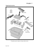
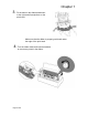
Chapter 1 •Unpacking the printer * The packing style is subject to change without notice.
Chapter 1 • Connecting the printer to the power source • Make sure that the power switch is set to off. Connect the printer with the supplied power cord to an AC outlet. • The AC outlet shall be installed near the printer and shall be easily accessible. Connect the AC power plug to an AC outlet of the voltage designated on the rating label on the back of the printer. • Connecting the printer to the computer 1. Parallel interface Make sure the power switch is turned to off.
Chapter 1 • Installing the ribbon cassette 1. Turn off the power. Open the front cover. Move the print head to the left end position. Caution Do not touch the print head immediately after printing because it may be too hot. 2. Remove the Red Locking material located at the center of the ribbon cassette, attach the cassette, as shown below.
Chapter 1 3. Fit the holes in the ribbon attachment to the right and left projections on the print head. Make sure that the ribbon is properly positioned under the edge of the print head. 4. Turn the ribbon feed knob counterclockwise to remove any slack in the ribbon.
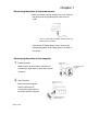
Chapter 1 • Setting up the front Paper Rack & Rear Tractor Assembly • The tractor can be installed in front or rear side; 1. Attach the paper rack holders (right & left) Press the holders until you hear a click. When removing the paper rack holder, use the remove lever, located above the holder. 2. Attach the paper rack to the paper rack holders. 3. Lower the paper rack. Snap the paper rack securely onto the holders.
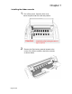
Chapter 1 4. Move both paper guides to the right & left end. 5. Insert the connector on the tractor assembly to the mating connector on the rear side of the printer. Then install the rear tractor. 6. Both tractors can be moved right and left to meet the width of paper or printing data when the lock lever is released. CAUTION Do not put your finger under the tractor cover • Set fanfold paper onto the tractors.
Chapter 1 7. Slide the paper path lever to the symbol or the position of "AUTO". The lever position should be at "AUTO" when using the printer driver. 8. Specify the page length. 7 PAGE LGTH REAR TR Fanfold paper size marked on package (Example) When the page length is not specified, refer to the number of sprocket holes to determine the page length. No. of holes x 0.5 inch equals the page length. The above example (8 holes) relates to 4-inch fanfold length.
Chapter 1 9. Perform a trial print sample after connecting the printer to the computer. Adjust the tractors left or right to align the left print margin. Adjust Menu Item “3 TOF ADJUST” to correct vertical alignment.
Chapter 1 • Setting up the Manual cut sheet 1. Attach the paper rack holders (right & left) and the paper rack. Refer to Chapter 1, “Installing Paper Rack & Rear Tractor Assembly”. 2. Adjust the printing position by sliding the paper guide right or left. When loading a wide paper, adjust the right paper guide.
Chapter 1 3. Slide the paper path lever to the appropriate symbol, or the "AUTO" position. The lever position should be at "AUTO" when using the printer driver. Auto Sheet Feed Rear Tractor Paper Rack / Manual Front Tractor 4. Connect the printer to the computer and perform a trial printing. The display appears as below along with the sound of a buzzer when the printer receives the data from the computer.
Chapter 1 5. Insert a cut sheet paper straight along the paper guide. If paper is inserted slightly skewed, the printer detects it, and adjusts the paper automatically. NOTE: If paper is extremely skewed (i.e. paper is over the guide), the printer may not adjust the skew. In this case, move the paper guide to the left a little, then insert the paper at some distance from the paper guide. In case of vertical offset the printing position should be adjusted by Menu Item “4 TOF ADJUST”.
Chapter 1 • Setting up the Front tractor 1. Attach the paper rack holders (right & left) to the printer as shown below. Place the bottom of the holder into the chassis, rotate the holder up until you hear a click. 2. Insert the tractor connector (left side) to the mating connector on the front side of the printer. 3. Attach the tractor to the paper rack holders as shown below.
Chapter 1 4. Vertically attach the paper rack to the holders as shown below. 5. Both tractors can be moved right and left to meet the width of paper or printing data when the lock lever is released. CAUTION Do not put your finger under the tractor cover.
Chapter 1 6. Lower the paper rack down and then press the paper rack securely onto the paper rack holders. 7. Slide the paper path lever to the appropriate symbol, or the "AUTO" position. The lever position should be at "AUTO" when using the printer driver.
Chapter 1 8. Specify the page length. Menu Item 6 PAGE LGTH FRONT TR Check the fanfold paper size marked on the package. 9.Perform trial printing after connecting the printer to the computer. Adjust the tractors left or right to align the left print margin. Adjust Menu Item “2 TOF ADJUST” to correct vertical alignment. 2 TOF ADJUST FRONT TR When using the front tractor along with the CSF, cut the fanfold paper by hand, not by the paper cutter.
Chapter 1 • Setting up the CUT SHEET FEEDER (optional) 1. Attach the paper rack holder (right & left) and the paper rack. 2. Move both paper guides to the right & left end. 3. Attach the hoppers and center support to the cut sheet feeder.
Chapter 1 4. Attach the cut sheet feeder to the back of the printer. CAUTION Use both hands and hold firmly at each end when lifting the cut sheet feeder. Personal injury can occur if the CSF unit is dropped. 5. Shuffle the paper as show below. NOTE: Page 22 of 46 Be sure to shuffle sheets sufficiently before setting them. Otherwise, several sheets of paper may be fed at the same time resulting in a paper jam.
Chapter 1 6. Set the CSF release levers to the front to release the paper bin. 7. Set the paper guide lock lever to the “Release” position to adjust the paper width. Set the paper guide lock lever to the Locked position.
Chapter 1 8. Set the CSF release levers to the back to close the paper bin. 9. Slide the paper path lever to the symbol or the position of "AUTO". ASF The lever position should be at "AUTO" when using the printer driver.
Chapter 1 10. Perform trial printing after connecting the printer to the computer. In case of vertical offset, the printing position should be adjusted by Menu Item “5 TOF ADJUST”.
Chapter 1 • Installing the printer driver Windows 2000 Installation: 1. Select the desired driver provided on the CD shipped with your printer. 2. Open the driver folder and execute “SETUP.exe”. 3. Choose the Printer in the "Driver Installation Utility" window and Click the "Install" button. Driver Installation Utility -7350 -7350 4. If a "Hardware Installation" window pops up, select "Continue Anyway". 5. Wait for the “Installation Successful” message and press the EXIT button.
Chapter 2 • Control Panel The liquid crystal display (LCD) on the control panel displays the processing conditions of the printer and the setting of the functions. The keys on the control panel provide various functions. 1.
Chapter 2 2. Function keys 1. ONLINE Press the ONLINE key to change the printing enabled (online) state and printing disabled (offline) state. 2. RESET (ALT + RESET keys) Press the RESET key while you press the ALT key, a buzzer will sound. Then “INITIALIZE” is displayed on the LCD if the keys are released. The printer is reset immediately. 3. SPEED Press the SPEED key to display the currently selected printing quality on the LCD.
Chapter 2 6. ENTER The setting are saved by pressing the ENTER key. 7. ALT The following functions are executed by pressing the corresponding key while you press the ALT key. FF→ Form Feed MICRO LF → Micro Line Feed MICRO RLF → Micro Reverse Line Feed MENU → Setup Menu RESET → Resets the printer 8. TEAR OFF Press the TEAR OFF key, and the printer automatically feeds the perforation of the paper to the paper cutter position (for fanfold paper only).
Chapter 2 9. EJECT/LOAD ●If the EJECT/LOAD key is pressed when fanfold paper is loaded, the paper is fed back to the parking position. When it is pressed when a cut sheet paper is loaded, the paper is ejected. ●When the EJECT/LOAD key is pressed when fanfold paper is at the parking position, the paper is loaded to the TOF position. ●When the EJECT/LOAD key is pressed with no paper in the manual mode, AUTO SKEW mode is turned on and off.
Chapter 2 3. LCD Current paper path and the User No. are displayed.
Chapter 2 4. Lamps (LED Indicators) ONLINE (Green) ON: Printing is enabled. OFF: Printing is disabled. Blinking: The cover is open, or the printer is in the head temperature protect mode. SPEED (Green) ON: LQ speed printing. SLOW FLASH: Draft printing OFF: NORMAL MQ speed printing. FAST FLASH: HIGH 2 (High Speed) Draft printing. ERROR (Amber) ON: No paper is detected or other operational error occurred. OFF: No error is detected. Blinking: A functional error has occurred(such as home sense error.
Chapter 2 • Paper path lever The lever for changing the paper path. Position Front tractor Paper path F Manual/Cut Sheet Rear tractor Cut Sheet Feeder The required paper path can be selected by the setting of the lever. The paper path command is valid when selecting the “AUTO”. The lever position should be at “AUTO” when using the printer driver. Before changing the paper path, remove the paper inside the printer by pressing the EJECT/LOAD key.
Chapter 2 • Head adjustment lever This lever is for adjusting the gap between the print head and the paper. AUTO 7 1 The lever position should be at "AUTO " normally, which adjusts the gap in accordance with the SETUP MODE. When " AUTO " is selected on the panel, the printer measures the paper thickness and adjusts the gap between the print head and the paper automatically. 1 HEAD ADJUSTMENT In case that the graduation 1 - 7 is selected, the gap between print head and paper is fixed.
Chapter 3 • How to use the setup modes The printer has setup modes, i.e., function setting modes that are unique to this printer. The setup modes enable various printer functions to be set up with the function keys on the operation panel. This section provides an outline of the setup modes and the details of the setup functions. 1. Keys used for setting 1. Menu key Press the ALT+MENU key to enter the MENU MODE. + 2. Menu selection keys These keys are used to change the displayed menu.
Chapter 3 2. Setting example The following is the example to change the page length of fanfold paper from 11 to 8 inch. 1. Press the MENU key while depressing the ALT key. 1 HEAD ADJUSTMENT + 2. Select #6 with the or key. 6 PAGE LGTH FRONT TR 3. Press the key. 4. Press the or key to display "8 INCH" on the LCD. 5. Press the ENTER key. "8 INCH" is marked with on asterisk. 6 PAGE LGTH FRONT TR 6. Press the MENU key. The setting is automatically saved and the printer is initialized.
Chapter 4 • How to use set Power Up User Format This printer has a total of 6 User Formats. Various SETUP Modes as described in Chapter 3.1 & 3.2 can be saved in each of the 6 User Formats. Menu “18 PWR UP AS” can be used to select one of the 6 User Formats as the Power Up Default. The Power up user format is normally identified with a number on the LCD display as shown below. Indicating the printer is set to User Format 1 as power up default.
Chapter 5 • How to solve the problem 1. Printing speed is slow. Push the key SPEED and select the mode High-speed. LQ NORMAL HIGH 2 DRAFT 2. Printing is light Check the condition of ribbon cassette. If the surface of fabric becomes whitish, replace the cassette with a new one. Head Adjustment may not be adequate. Adjust menu setting #1 HEAD ADJUSTMENT. When multipart forms are used for printing. Select “ON” , menu setting HIGH IMPACT key. 3. Paper jam often occurs. Head Adjustment may not be adequate.
Chapter 5 5. The message PAPER JAM appears, though paper is not jammed. The paper jam sensor may not function properly if the sensors on the tractors are exposed to a direct light or sunlight. Adjust the position of the printer not to be exposed to an excessive light. Check if any dark printing is near the sprocket hole on the backside of fanfold paper or media. Black print or holes detected by the paper sensors will cause erroneous errors.
Chapter 5 9. Unexpected printing results. A gap occurs between the print start position and the top end of paper. Adjust the gap by setting #2 - #5 TOF ADJUSTMENT in the SETUP menu. (The setting on SETUP differs in accordance with each paper path) The unexpected printing position occurs right and left. Adjust the tractors position moving the paper guides right and left. Adjust #14 LEFT MARGIN in the SETUP menu to adjust the position.
Chapter 5 2. Operational error message • The print head is being cooled to prevent it from overheating. The ONLINE lamp blinks. The print head has become too hot during high-density printing. When this message is displayed, the printing speed is reduced or printing stops. When the print head temperature drops, the printer restarts printing. • This error message indicates that fanfold paper is not fed back into the tractor assembly properly. Cut the paper to remove it.
Chapter 5 A paper jam occurs at the front tractor. Pull the ejected paper outward gently and press the ONLINE key to restart printing. When the PAPER JAM still remains, remove all paper and reinstall the paper into the tractor properly and press the ONLINE key. Re-adjust the gap between the print head and the paper, by menu #1 HEAD ADJUSTMENT. When the paper thickness may be not constant, set YES at menu #45 LF STABLE.
Chapter 5 • This error occurs if the printer detects that a cut sheet paper is manually loaded with excessiveskew. • The ERROR lamp blinks, and the buzzer sounds three times. The paper is ejected and the printer enters the offline state. Load paper again. If it is loaded straight, the printer enters the online state. • This error occurs if the front cover is opened. The ONLINE lamp blinks. Closing the front cover will remove the cause of this error.
Chapter 6 • Printer specifications Printing Method Print Head Maximum column Print speed Multipart printing Line feed speed Line feed pitch Paper path Head adjustment Interface Input buffer Emulation Other functions Font typeface USER Formats Page 44 of 46 Serial impact dot matrix 24pin 136 columns (10cpi) LQ 150 CPS (10cpi) NORMAL (NLQ) 200 CPS (10cpi) DRAFT (HQDR) 300 CPS (10cpi) High 2 (HS Draft) 400 CPS (10cpi) SSD 600 CPS (15cpi) Standard 1+5p DARK 1+7p 36 LPI 1/360 INCH Front tractor or rear tract
Chapter 6 • Other specifications Power supply AC 120 V, 60Hz (USA and Canada) AC 220-240V, 50-60Hz (Europe and Asia) Power consumption Draft self Stand-by Operating temperature Operating humidity Dimensions Weight • Paper specifications Available paper size • Fanfold paper 170watt s 40watts 2.3A (120VAC) 1.3A(220-240VAC) 0.6A (120VAC) 0.4A(220-240VAC) Energy Star 15watts 5 to 40o(41 to 104o) 20 to 80% (No condensation) 25”(W) x 18.3”(D) x 11.6”(H) 50 lbs Paper width 8”~15” Paper thickness 0.
AMT Datasouth Corporation 803 Camarillo Springs Road, Suite #D Camarillo CA, 93012 1-800-215-9192 Page 46 of 46