Documax 5380 24-Pin Dot Matrix Printer User’s Guide © March 2013, AMT Datasouth Corp.
Copyright Declaration Information in this manual is subject to change without notice and does not represent a commitment on the part of AMT Datasouth Corporation. No part of this manual may be reproduced or transmitted in any form by any means, for any purpose other than the purchaser’s personal use, without the expressed written permission of AMT Datasouth Corporation. Trademark Credits: EPSON is a registered trademark of Seiko Epson Corporation.
Table of Contents User Caution...................................................................................................................5 Packaging .......................................................................................................................6 Unpacking the printer .................................................................................................................................... 6 Removing protective material ................................................
Diagnostic Testing ....................................................................................................... 32 ASCII Self-test ............................................................................................................................................. 32 Print head pin test ........................................................................................................................................ 32 Hex dump mode ...................................................
Operational safety User Caution CAUTION To avoid burns, do not touch the print head immediately after printing. Do not put your fingers under the tractor covers while loading fanfold paper. Cautions in setting up Unplug this product from the power outlet before cleaning. Do not use this product near water. Mechanical and electrical repairs should be conduct by qualified service personnel. CAUTION Unpack the printer.
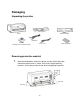
Packaging Unpacking the printer Paper Support Printer Ribbon Cartridge USB Cable CD ROM (Including user's manual and driver) Power Cord Quick Start Guide Removing protective material 1. Open the packing box, remove the printer and tear off the fiber tape around the printer cover as shown. Save all the original packing materials, so that they can be reused when transporting the printer.
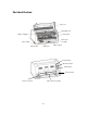
Part identification Top Cover Gap adjust lever Ribbon cartridge Control panel Pinch roller assembly Power switch Paper guide Paper support Print head Serial interface Ethernet interface USB interface AC Power inlet Paper select lever Paper Tractor assembly -7-
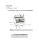
Installation Installing paper support 1. Open the top cover, align the A, B, C tabs over the printer corresponding A, B, C slots, and then press downward to fasten. Top cover Guide Slots Paper support Paper guide Note: When transporting the printer remove the paper support. Open the Top Cover, lift up on the left and right side of the paper support evenly until removed. The paper guide should be positioned all the way to the right for proper paper left edge alignment.
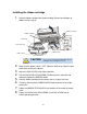
Installing the ribbon cartridge 1. Remove ribbon cartridge from the plastic bag. Remove and dispose of ribbon retainers (qty-2). 2 Ribbon feed knob 7 3 Ribbon cartridge Gap lever Print head Head carrier pin 4 6 Pinch roller assembly 5 Ribbon mask Ribbon guide CAUTION Do not touch the print head immediately after printing because it may be too hot. 2. Make sure the power switch is OFF. Open the front cover. Move the print head to the center of the printer. 3. 4.
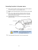
Connecting the printer to the power source 1. Make sure that the power switch located on the left side of the printer is set to OFF. Press the “O” side of the power switch. 2. Plug one end of the provided power cord into the printer’s power supply inlet. 3. Make sure the voltage required by the printer matches that of your electrical outlet. Refer to the voltage designated on the rating label located on the back of the printer. 4.
Connecting the printer to the PC Note: The Documax 5380 printer can use a USB, Ethernet, or Serial cable to connect to the PC. Parallel interface is optional. 1. Install desired interface connection. Make sure that the power switch is turned to OFF and connect the appropriate cable(s) to the printer and the computer. USB CABLE CONNECTION USB interface USB cable Plug the USB cable A end (flat shape) into the computer's USB interface.
SERIAL CABLE CONNECTION Serial interface Screw Serial cable Cable type must be NULL MODEM Turn OFF both the computer and the printer. Plug the serial cable 25-pin male connector securely into the printer's serial interface and the other end into the computer. Secure cable with connector screws, both ends. PARALLEL CABLE CONNECTION (Optional) Parallel interface Wire clips Parallel cable Turn OFF both the computer and the printer.
Loading Paper Paper thickness adjustment Adjust the gap lever inside the printer on the front right side to feed thicker paper and forms. The lever moves the print head relative to the platen so that there is more room for the paper. Refer to the label mounted on the inside of the Top Cover and adjust thickness accordingly. MEDIA GAP OTHER 7~9 6~7 5 4 2~3 SINGLE MULTI-PART 1. 5~6 4 3 Gap lever 2 0~1 Loading cut-sheet paper/forms 1.
2. Position the paper guide to the furthest right position. Paper Guide 3. Pull tray extension out for long paper/forms requiring extra support. Tray Extension 4. Insert the paper as shown below, the paper is fed into the printer automatically.
Loading tractor paper 1. 2. Set paper thickness lever, refer to “Loading Paper” section. Set the paper select lever located on the back side of the printer to Tractor Paper (down position). Tractor paper Paper select lever 3. Loosen the left and right tractors by lifting up on lock levers. Adjust the left tractor to the home position (“▽” denotes home). Adjust right tractor to approximate paper width. Lock left tractor into place by pressing down on the lock lever.
4. Move the tractor paper guide to the middle of the tractor assembly. Tractor Paper Guide 5. Open the tractor covers and place the paper onto the sprocket pins. Proper Paper Hole Alignment Tractor Covers 6. Close the tractor covers and adjust the right tractor to ensure the paper is flat. Then press down the lock lever.
Tractor paper tear off When the printer leaves the factory, the tractor paper tear off function is enabled. At the completion of a print job, the printer will feed the tractor paper to the tear off position automatically. Paper can be torn off along the window edge. The printer default setting can be disabled. In a disabled mode, press the ONLINE key to advance the paper to the tear off position. ADJUSTMENT ~ 1.
Top of form adjustment The top of form setting determines the margin between the top of paper and the first printed line (the top margin). The top of the first printed line is the zero position. Advancing the paper is a positive value, reversing the paper is a negative value. When the menu setup mode has specified the left black mark or right black mark, this is defined as the distance from the black mark to the left or right edge of paper. TOF ADJUSTMENT ~ 1.
Print Driver Installation Win2000 (XP~Vista~Win7) 1. Open the driver folder on the CD shipped with the printer. Then open the subfolder for your version of Windows. 2. Click on the “Setup.exe” file to begin the installation utility. Have your printer ready to connect when instructed. 3. 4. 5. If a pop-up window occurs, click “Install driver anyway”. Click on the “Documax 5380” icon to select the driver. Click on the “Install” button to begin the driver installation.
8. Right-click on the Documax 5380 icon Properties”. 9. Choose the “Ports” tab and select the correct interface port for your printer. For Ethernet port IP recognition, run “NetFinder” utility on CD. 10. and select “Printer End of procedure. Printer settings via driver 1. 2. Open the “Devices and Printers” window from the PC Start button. Right-click on the Documax 5380 icon Properties”. and select “Printer 3.
7. Click on “Printer maintenance” printer setup features.
8. Click on “Advance printer setup” additional printer setup features. to access Advance Printer Setup Menu 9. Return to main menu and click on “OK” to exit and save settings.
Control Panel Indicator LED’s Indicator LED Off On ONLINE (green) —— Lights when the printer is online. The printer is offline or error state. Blink COPY {BOLD} (green) The printer is in the normal mode. The printer is in the copy 1 mode. The printer is in the copy 2 mode. SPEED (green) The printer is in the Letter Quality mode. The printer is in High Speed Draft mode. The printer is in Super High Speed Draft mode.
Printer settings via printer control panel 1. With ribbon installed, print current settings by pressing the LOAD/EJECT and LF/FF keys while turning ON the printer power switch. Release keys and load cut sheet paper to print settings. 2. Review printout. The highlighted settings (gray background) depict current feature setting. 3. In the online mode, press and hold the LOAD/EJECT key, and then press the ONLINE key. Hold keys simultaneously for 3 seconds.
Factory default settings AM AMT Documax 5380 V2.0 U11 2013/01/15 SN: XXXXXXXXXXXXXXXXXXXX MAC:XX-XX-XX-XX-XX-XX DHCP:YES IP:10.0.0.1 Subnet: 255.255.255.0 Gateway: 255.255.255.255 Factory default settings LANGUAGE EMULATION CHAR. MODE CHINESE OKI CHINA FONT ENG PITCH SANS SER 12 CPI CHI PITCH 7.5 CPI SLASH ZERO ON INTL CHAR SE JAPAN COURIER 15 CPI PRESTIGE SCRIPT PROPORTIONAL OCR-B OCR-A ORATOR FRANCE NORWAY GERMANY DENMARK2 U.K.
Printer setting definitions Options Description LANGUAGE Specify the printer menu language as English or Chinese. EMULATION Specify printer's control commands. CHAR. MODE Select ASCII or Chinese character mode. FONT Specify a kind of ASCII character font. If the print data contains font instruction, the printer gives priority to print data instruction. (Only valid when CHARACTER MODE is set to ASCII) ENG PITCH Specify the ASCII character spacing in characters per inch (cpi).
PRINT DIR Select the printing direction of the print head: unidirectional, bidirectional or Auto selected via software. HIGH DENSITY After selecting this function, printing definition will be enhanced while the print speed is reduce. QUIET MODE Disable or enable the low noise function. When this function is on, print speed will be reduced. AUTO LF If this function is on, the printer will advance the paper one line automatically after receiving every carriage return instruction.
Ethernet Interface Settings NetFinder search 1. Power on the printer, connect the LAN Ethernet cable to the printer port located on the back of the printer. Verify the Ethernet port LED indicates a normal connection. Yellow LED ON OFF 2. Green LED Blink OFF Description Connecting to network Not connecting to network Run NetFinder software (provided on CD shipped with the printer).
Search results: Model: Documax 5380 IP Address: 192.168.0.240 [Dynamic] MAC Address: 20-2C-B7-00-3F-03 Should the printer not be found during the search, check to see if the network firewall is blocking the search results. Temporally disable the firewall and restart the NetFinder search. In order to search and set the printer’s IP address conveniently for the first time, the factory default setting is DHCP mode which assigns the IP address dynamically.
2. Select the printer information to be modified by clicking on the displayed printer (black frame appears), click “Assign IP” button. Model: Documax 5380 IP Address: 192.168.0.140 [Dynamic] MAC Address: 20-2C-B7-00-3F-03 Model: Accel 7450 IP Address: 192.168.0.120 [Dynamic] MAC Address: 20-2C-B9-00-4F-04 3. Uncheck “Use DHCP” and set the desired IP address, Subnet Mask and Gateway in the dialog box. If there is no gateway in the network, use 255.255.255.255. 4.
5. Run NetFinder again to verify the printer has been updated with Static IP. Model: Documax 5380 IP Address: 192.168.0.240 [Static] MAC Address: 20-2C-B7-00-3F-03 Model: Accel 7450 IP Address: 192.168.0.120 [Dynamic] MAC Address: 20-2C-B9-00-4F-04 6. 7. Exit NetFinder software. 8. Right-click on the Documax 5380 icon Properties”. 9. Choose the “Ports” tab and select the correct IP interface port for your printer. 10. Open the “Devices and Printers” window from the PC Start button.
Diagnostic Testing ASCII Self-test 1. Power on the printer while pressing the ONLINE key. Pressing the ONLINE key a second time will stop printing. Reboot the printer to exit ASCII test mode. ASCII TEST MODE AMT Documax 5380 VX.X XXX XXXX/XX/XX SN: XXXXXXXX MAC: XX-XX-XX-XX-XX-XX DHCP: YES IP: 10.0.0.1 Subnet: 25 !"#$%&’( )*+-./0123456789:;<=>?@ABCDEFGHIJKLMNOPQRSTUVWXYZ[\]^_`abc !"#$%&'( )*+-./0123456789:;<=>?@ABCDEFGHIJKLMNOPQRSTUVWXYZ[\]^_`abcd "#$%&'( )*+-.
Interface Specification This Documax 5380 printer can be configured with 2.0 Full-Speed USB interface, RS-232 serial interface, 10/100Base-T Ethernet interface or the optional Centronics (IEEE1284 NIBBLE) parallel interface USB 2.0 full speed interface 1. The following table provides the standardized contact terminating assignments for Series “A” and Series “B” connectors. Pin number Name Color 1 VBUS Red 2 D- White 3 D+ Green 4 GND Black 14 23 Serial DB-25 interface 1.
2. Pin description: Pin Signal Name Direction 1 FG Frame Ground 2 TXD Transmit Data OUT 3 RXD Receive Data IN 4 RTS Request to Send DTR DTR CTS OUT 5 CTS Clear to send IN 6 DSR Data set ready IN 7 GND Ground 8 DCD Data carrier Detect 6 DSR DSR 1 DCD 8 DCD 2 0 GND TXD GND RXD 7 CTS 5 2 3 2 3 TXD GND Printer 25TXD PIN connector GND RXD HOST 9 PIN connector IN … … DTR Data terminal ready 20 OUT … … 3.
When the DTR is low level, the printer is BUSY, it cannot receive the data from HOST. DTR is low level in the following conditions: The printer is offline. The data buffer of the printer is smaller than limited value. The printer has an error. X-ON/X-OFF Protocol ~ Send the X-ON (11H) code to the HOST from the printer through TXD, which indicates the printer is FREE and can receive data from HOST.
Parallel interface 1. Standard Centronics (IEEE1284 NIBBLE) parallel interface connector, DB-36 pin type connector. The parallel interface has the following characteristics: Data format: 8-bit Synchronization: STROBE pulse Handshaking: BUSY and ACKNLG signals Signal level: TTL compatible Signal Pin No. Return Line Pin No.
Printer Maintenance Carriage shaft Pinch Roller Assembly Paper platform Paper platform Paper feed sensor CAUTION Disconnect AC Power Cord Do not touch the print head immediately after printing because it may be too hot. Cleaning period Periodical cleaning: every six months or every 300 running hours. Cleaning tool: dry cloth (use soft cloth to clean metal & plastic parts). Clean the paper platform Pull out the Pinch Roller Assembly and turn it over. Wipe away paper and ink debris.
Printer Specification - 38 -