Fastmark 4600 PLUS Series Thermal Transfer Barcode Printer User’s Guide Document #140106B February 2012
Table of Contents Getting Started .................................................................................................... 5 Unpacking ....................................................................................................... 5 Package Contents........................................................................................... 6 Placing the Printer .......................................................................................... 7 Connecting the Power Cord .........
Table of Contents Technical Reference ......................................................................................... 62 General Specifications ................................................................................. 62 Fonts, Bar Codes and Graphics Specification ........................................... 65 Interface Specifications ............................................................................... 68 ASCII TABLE .............................................................
IMPORTANT SAFETY INSTRUCTIONS AND OTHER NOTICES This printer complies with the requirements in Part 15 of FCC rules for a Class A computing device. Operation of this equipment in a residential area may cause unacceptable interface to radio and TV reception, requiring the operator to take whatever steps are necessary to correct the interference. Place the printer on a flat, firm and solid surface. Do not place the printer near a heat source or near water.
Getting Started Congratulations on choosing the AMT Datasouth Fastmark 4600 PLUS Series industrial barcode printer. This user’s manual describes the FM 4600 PLUS Series printer model features and will help you get to know your new printer. The manual includes a guide to operate the printer as well as related information on troubleshooting, maintenance, and technical reference. Illustrations are provided to help you quickly become familiar with the printer.
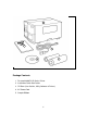
1 2 4 3 5 Package Contents 1. Fastmark 4600 PLUS Series Printer 2. Installation Quick Start Guide 3. CD Rom (User Guides, Utility Software & Drivers) 4. AC Power Cord 5.
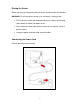
Placing the Printer Before setting up and connecting the printer you should consider the following. WARNING! Do not operate the printer in an area where it might get wet. Find a solid flat surface with adequate room for the printer and enough space above for media and ribbon access. Place the printer within cable distance of the host and printer (serial or parallel cable.) Isolate the power cord from other electrical cables. Connecting the Power Cord Connect the power cord as below.
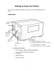
Getting to Know Your Printer The illustrations below describe parts and features of the FM 4600 PLUS Series printer. Front Panel LCD Message Display Control Panel LED’s and Switches Top Access Printer Models: TIA-200V (FM 4602 PLUS / 203dpi) Door TIA-230E (FM 4602 PLUS / Int. Ethernet 203dpi) Front Access TIA-320 (FM 4603 PLUS / 300dpi) Door TIA-320E (FM 4603 PLUS / Int.
LED Indicators There are three LED indicators on the front panel, READY, MEDIA and RIBBON. These indicators display the operation status of the printer.
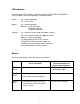
Notes: 1. You should perform a media calibration after installation and when changing to a different type or size of media. 2. Before calibration, you must load the media and ribbon properly and move the label sensor to the correct position avoiding holes. 3. After calibration the printer saves parameters to FLASH. Without correct calibration gap detection is easily lost during printing especially for small labels (less than 1.5 inches in height). 4. After self-test, the printer is in dump mode.
FM 4603 PLUS Series (300,PAL/PPLZ) FOR KEYBD If a barcode reader is connected, the display shows: FM 4602 PLUS Series (203,PAL/PPLZ) WITH B.C. READER FM 4603 PLUS Series (300,PAL/PPLZ) WITH B.C. READER If an abnormal condition occurs, a related message is displayed. For example: RIBBON OUT Setting Display Language The printer’s LCD display supports six languages: English, French, German, Italian, Spanish, and Portuguese. To select a language: 1. Press the PAUSE and CANCEL buttons at the same time.
Changing Settings from the Panel You may change settings using the front panel buttons of the FM 4600 PLUS series printer models. In addition you may also change settings via software Utility and data stream commands. Buttons FEED+PAUSE FEED+CANCEL Function Press to enter setting mode. (Don’t press over 1 second) Press to show next features. CANCEL FEED+CANCEL Press to select desired feature. To scroll through the list of values for the chosen feature.
Basic Printer Features and Parameter Settings , PPLA/PPLB. NOTE: Features can vary based on printer model. Do not change settings during printing or communication. Feature PRINT MODE Parameter Thermal transfer / Direct thermal Factory Default Thermal transfer AUTO CALIBRATE MODE CUT/PEEL OFFSET TPH VERTICAL OFFSET RECOVER PRINT CUTER INSTALLED PEELER INSTALLED READER INSTALLED WIN. CON. LIN. Mode 1~4 Mode 1 Calibrates on demand. -015 ~+.050 0 -.003~+.
Feature PARITY (RS232) Parameter Factory Default NONE NONE EVEN ODD LENGTH 8 DATA BITS 8 DATA BITS (RS232) 7 DATA BITS CLEAR FLASH YES/NO NO PRINTERS WITH ETHERNET DHCP ENABLE ENABLE DISABLE IP ADDRESS ###.###.###.### SUBNET MASK ###.###.###.### DEFAULT ###.###.###.### GATEWAY MAC ####.####.
Feature PEELER INSTALLED COUNTING Parameter YES NO UP DOWN MEDIA GAP SENSOR TYPE BLACK BAR PRESENT DISTANCE ABS DARKNESS TRIM DARKNESS BAUD RATE (RS232) Factory Default NO Remarks DOWN GAP .0~040” .87” 0~30 0 Select for media characteristics. Once changed make sure to calibrate before printing. Appears only when BACKFEED enabled.
Internal Parts and Features Ribbon Pick-up Spindle Ribbon Supply Spindle Media Supply Spindle Rear Feed Slot Head Latch Thermal Printhead Paper Sensor Guide Paper Drive Roller 16
Peeler Option Cutter Module 17
Loading Ribbon and Media This section describes how to load ribbon and media. Loading a Ribbon Note: This section can be referred to, when transfer thermal printing is used. The steps below are based on ribbon wound ink-side in as an example. 1. Lift the top cover and front access door to expose the media compartment.
2. Turn the head latch counter-clockwise and open the bracket. (Figure 2) 2 Head Latch Bracket 3. Unwrap the ribbon and separate the ribbon roll from the bare core. Insert the ribbon roll onto the ribbon supply spindle.
4. Lead the ribbon through the print head module. (Figure 4) 5. Attach the edge of the ribbon onto the bare core and wind it a bit onto the core. Make sure the coating side of the ribbon is face down. 4 Print Head Module Bar Core 6. Insert the core onto the ribbon pick-up spindle. (Figure 5) 5 Ribbon Pick-up Ribbon Pick-up Spindle Spindle 7. Turn the pick-up spindle to ensure the ribbon is tightly wound.
Loading Media The FM 4600 PLUS series printers offer three different loading modes: standard, peel-off, or with a cutter. Standard mode allows you to collect each label freely. Peel-off mode peels backing material away from the label as it prints. After the label is removed, the next label prints. Cutting mode automatically cuts the label after it prints. Standard Mode 1. Insert the media roll into the media supply spindle and move the media guide to the inside.
2. Turn the head latch counter-clockwise and open the bracket. Remove the outside media guide.
3. Lead the media through the print head module and under the paper sensor guide. (Figure 8) 8 Print Head Module Paper Sensor Guide Module 4. Return the outside media guide, close the bracket, and hook the head latch.
5. Close the top cover and the front access door and turn on the printer, or press the “FEED” button if the printer is already on.
Peel Off Mode Follow steps 1 to 3 in “Loading the Media – Standard Mode” above. 1. From the leading end of the media roll remove enough labels to expose 6-inches of backing/liner.
2. Lead the media backing/liner through the print head module. (Figure 12) 12 1 Media Backing/Liner 1 Print Head Module 3. Push down the peel-off mechanism release lever and lead the media backing/liner under the peeler module.
4. Close the peeler module using the peel-off mechanism release lever. (Figure 14) 14 Peel Lever Dispenser Module 5. Close the top access door and turn on the printer or press the FEED button if the printer is already on. (Figure 15) 15 1 1 Media Backing/Liner Notes: The FEED button does not make the printer peel. For peeling to occur when the panel setting is properly enabled. Make sure the peeler sensor is out of the ribbon path when installed.
Cutting Mode Follow steps 1 to 3 in “Loading the Media – Standard Mode” above. 1. Insert the media into the print head module and under the paper sensor guide.
2. Return the outside media guide, close the bracket, and hook the head latch. (Figure 17) 17 81 1 Head Latch Bracket Outside Media Guide 3. Close the top access door and turn on the printer or press the FEED button if the printer is already on. The printer will then feed the labels through the cutter automatically. (Figure 18) Cutter 18 Note: The FEED button does not make the printer cut. For cutting to occur when the panel setting is properly enabled.
Control Panel Operation Front Panel The front panel includes - LCD display - 3 LED status indicators (READY, MEDIA and RIBBON) - 3 control buttons (FEED, PAUSE and CANCEL) LCD display LED indicators Control buttons 30
LED Indicators There are three LED indicators on the front panel, “READY”, “MEDIA” and “RIBBON”. These indicators display the present status of the printer. The Ready LED indicates the following conditions: READY ON - The printer's power is on, unit is ready to print. Off - The printer's power is off. Blinking - Error condition (see Troubleshooting section for details) The Media LED indicates the following conditions: MEDIA ON - Media is installed and ready for Normal operation.
Buttons Depending upon the printer model and current mode, the Front Panel buttons serve multiple functions. Refer to the following tables for their specific functions. Pressed and held down during Power UP Upon completion of the desired function the printer will go into a READY condition. Button FEED/CONFIG PAUSE/CALIBR CANCEL/RESET Function The printer performs an internal Self-Test and prints a Configuration Report. LCD displays "SELF TEST".
Pressed during normal operation Button Function FEED The printer will Feed a one label. PAUSE The printer will begin blinking the READY LED. If printing the printer will STOP printing, and the READY LED will blink. If pressed a second time the printer will resume normal operation. Models will blink the READY LED and display PAUSE on the LCD display while in the Paused condition. CANCEL The printer will Stop printing and delete any further information in the printer's buffer.
LCD Display The front panel is equipped with a 2 row by 16-character display. The basic function of the display is: - Display the printer status - Display the printer settings - Display's prompts requesting input data from a keyboard or barcode reader. Standard Printer After power ON the following message is displayed on the LCD (203, PAL/PPLZ) The first parameter is either 203 or 300. It indicates the print resolution.
Front Panel Set-up Menu The Set-up menu is a list of printer features that affect the basic operation of the printer. These are functions that may not normally be selected using software commands. Value settings that are changed using the keypad are stored into memory and are retained when power is cycled. Value settings that are changed using software commands are temporary changes and are not retained when power is cycled.
Procedure to Enter into Set-up Mode 1. Power on the printer. 2. When the “ READY” message is displayed on the LCD, press [PAUSE] once to enter off-line mode. Press and hold [FEED] and then [PAUSE] buttons. Release buttons. 3. Press and hold [FEED], then press [PAUSE] button repeatedly to scroll to the feature that you want to change. 4. Press [CANCEL] button once to select feature. 5.
Typical Set-up Control Panel Features (features may differ among models) Feature Item Value Factory Default PRINT MODE Direct Thermal or Thermal Mode Direct Thermal MAC ADDRESS ####-####-#### Printer Specific DEFAULT GATEWAY ###.###.###.### Printer Specific SUBNET MASK ###.###.###.### Printer Specific IP ADDRESS ###.###.###.
PALTM Print and Program Overview Printers featuring PALTM Print and Program ability can be used in several ways in any given environment. This section describes 3 common ways this advanced capability is used. For help and assistance determining the best way to use this ability in your situation, please consult your sales representative. Traditional Printing This environment represents the most common use of printers. Generally a single print job (PALTM print sequences) generates a single label.
Using a PALTM Print and Program capable printer solves this problem. In this case a PALTM program is written which interprets a data stream normally sent to the legacy device being replaced. This program is stored on the printer and is automatically executed each time the printer is powered on. This program is able to produce a new label format based on this legacy data. Even though the host computer is sending the exact same legacy data to the printer, the label format can be completely different.
The Standalone Application program is stored in the printer memory and can accept input from a PS/2 keyboard, bar code scanner, or other serial devices such as an electronic scale. These programs may use the printer’s LCD to prompt for user input and may also include databases. Unlike other bar code printers that allow basic static forms to be loaded in the printer, PAL TM Print and Program capable printers provide advanced abilities.
Calibration & Configuration This section discusses calibration, printing configuration and resetting the printer to factory defaults. Performing Calibration After the media is loaded, please perform media calibration to calibrate the label sensor in advance. 1. Turn off the printer 2. Press and hold the PAUSE button and turn on the power. 3. When “CALIBRATION …” is displayed on the LCD , and both READY and MEDIA indicators blink, release the PAUSE button.
Printing a Configuration Report To perform a self-test and print a configuration report: 1. Turn off the printer. 2. Press and hold the FEED button while turning on the power. 3. When “SELF-TESTING …” is displayed on the LCD and the READY indicator blinks, release the FEED button. NOTE: Printers with Ethernet will take 20 second for this process, the PAUSE button must be pressed during that period. 4. The printer prints out a configuration report. 5.
Resetting to Factory Default Settings To reset the printer to factory default settings: 1. Turn off the printer. 2. Press and hold the CANCEL button and turn on the printer. 3. When “E2PROM RESET …” is displayed on the LCD and the READY indicator blinks, release the CANCEL button. NOTE: Printers with Ethernet will take 20 second for this process, the PAUSE button must be pressed during that period. 4. When “READY” is displayed on the LCD, the READY indicator stops blinking but remains illuminated. 5.
Computer Connections This printer comes with USB interface, a standard Centronics parallel interface, and a nine-pin Electronics Industries Association (EIA) RS-232 serial data interface. USB Interface Requirements The Universal Serial Bus (USB) interface is version 2.0 and 1.1 compliant and provides a full-speed (12Mb/s) interface that is compatible with your existing PC hardware. The USB’s “plug and play” design makes installation easy. Multiple printers can share a single USB port/hub.
Serial (RS-232) Port The required cable must have a nine-pin "D" type male connector on one end, which is plugged into the mating serial port located on the back of the printer. The other end of the cable connects to a serial port on the host computer. For technical and pin-out information, please refer to the Technical Reference in this manual. Note: 1. Centronics allows a much higher communication speed than serial. 2. The pin assignment of serial cable is different from PC.
Ethernet Module Status Indicators LED Status Both Off Blinking Green Amber Description No Ethernet link detected. The printer waits for printer ready. It will take about 20 seconds to be ready.
Ethernet LED Indicators Green LED Amber LED 47
Communicating with the Printer The bundled printer driver can be applied to all applications under Windows 2000/ 2003/ XP/ Vista/ Windows 7, supporting 32-bit/ 64-bit operation systems. With this driver you can operate any popular Windows software applications including Bartender editing software or MS Word, etc., to print to this printer. The screens included for these steps are taken from Windows XP; steps in other versions of operation systems are similar.
1. Turn off the printer. Plug the power cable into the power socket on the wall, and then connect the other end of the cable to printer's power socket. Connect an interface cable (i.e USB, Parallel or Serial) from the printer to the PC. 2. Turn on the printer. If the printer supports Plug-and-Play, and you have successfully connected it using a USB cable, then the Windows Add Hardware Wizard will automatically detect the printer and display a dialog that allows you to install a driver.
5. Assign the directory to keep Seagull driver, (for example: C:\Seagull) and click "Next". 6. Click "Finish".
7. Select Install printer drivers and Click "Next" 8.
9. Select the port of the printer and click "Next". 10. Enter Printer name and select "do not share this printer”, and click "Next".
11. Check all the data on the showing screen, if it is correct, click "Finish". Not Shared LT1 YES TIA-230E 7.1.8_M-0 12. After the related files have been copied to your system, click "Finish".
13. After driver installation is complete, click "Close". The driver should now be installed.
Troubleshooting Normally, if the printer is in not working properly, the "READY" LED blinks continuously, and printing and communication between the host and printer stops. LED and LCD Diagnosis Blinking LEDs indicate a problem.
Ribbon Problems LED/LCD READY and RIBBON LEDs LCD Display Indication Blinking RIBBON OUT Possible Problems Solutions Ribbon out Supply the ribbon roll Ribbon jam Recover the jam Ribbon sensor Replace ribbon sensor error Remarks Not applicable to direct thermal. Note: If you use direct thermal, set with panel, Windows driver or command.
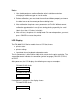
Light /Missing Print Print quality can be adjusted when light or missing print is primarily observed on the right or left side of the media. Figure 1 Figure 2 Light/Missing Print If the print discrepancy is as shown in Fig. 1, turn the Fine Adjustment Knob clockwise one setting (adjust counter clockwise for Fig. 2 correction), then try printing again to justify the print quality improvement. Repeat the same process until the print quality is well balanced on both sides of the label.
Miscellaneous If the host shows "Printer Time out" 1. Check if the communication cable (parallel or serial) is connected securely to your parallel or serial port on the PC and to the connector on the printer at the other end. 2. Check if the printer power is turned on. If the data has been sent, but there is no output from the printer. Check the active printer driver, and see if Seagull Driver for your Windows system and the label printer has been selected.
For unstable ribbon roll rotation, check the label path and make sure the head latch is securely closed. Poor printout quality: The ribbon may not be qualified. The media may not be qualified. Adjust the Darkness (heat temperature). Slow down the print speed. Refer to the following and clean the related spare parts. Recovery After correcting problems, simply press the CANCEL button or restart the printer. Make sure the LED’s are not blinking and remember to resend your files.
Caring for Your Printer Clean the following components of the printer using a cotton bud dampened with alcohol. Do not soak the cotton bud excessively. Note: Turn off the printer before cleaning. Cleaning the Print Head Clean the print head as follows 1. Turn off the printer. 2. Open the top cover to access the print head module 3. Remove the ribbon. 4. Rub the print head with a cotton bud moistened with alcohol. 5. Check for any traces of black coloring or adhesive on the cotton after cleaning. 6.
Cleaning the Roller Using a cotton bud moistened with alcohol, clean the roll and remove any attached glue. Note: Clean the roller after it has been in contact with foreign materials such as dust or adhesives. Cleaning the Media Compartment Clean the media compartment with a cotton bud that has been moistened with a mild detergent. Every time a media roll is printed, you should clean this compartment to reduce the incidence dust.
Technical Reference General Specifications FM 4602 PLUS Printing Method Printing Resolution Printing Speed Memory CPU Type Media Sensors IE FM 4603 PLUS Direct Thermal and Thermal Transfer 203 dpi (8 dots/.04”) Printing Width Printing Length / 300 dpi (12dots/.04”) Max 4.09” Max. 100” Max. 50” 2 ~ 6 ips Max.
Display LED indicator x3 Communi cation interfaces Centronic s parallel, RS-232 serial, USB Maximum Label Roll Diameter Media Types Ribbon Ribbon Size Compact Size Weight Power Source LED indicator x 3, Back-lit LCD Display 16 x 2-line, Multilingual Centronics parallel, RS-232 serial, USB, PS/2 keyboard Ethernet (FM 4602 IE / FM 4603 IE) 8”(203mm) OD on a 3”(76mm) ID core 7”(178mm) OD on a 1.
Agency Listing Operating Temperatur e Storage Temperatur e Driver Operating Systems CE, UL, CUL, FCC class A 40F~100F (4C~38C) -4F~122F (-20C~50C) Win 2000/ 2003/ XP/ Vista/ Windows 7 PPLA, PPLB PAL/PPLZ Printer Languages Real Time Clock (RTC) Options and Accessories optional standard Cutter Dispenser Rewinder Media Stacker Standalone KDU: ArgoKee RTC Font card Cutter Dispenser Rewinder Media Stacker Standalone KDU: ArgoKee 64
Fonts, Bar Codes and Graphics Specification The specifications of fonts, bar codes and graphics depends on the printer emulation. The emulation is a printer programming language through which the host can communicate with your printer. There are three printer programming languages, PPLA, PPLB and PAL/PPLZ.
Printer Programming Language B, PPLB Specification General Fonts Symbol Sets (Code Pages) FM 4600 PLUS Series 5 fonts with different point sizes 8 bits: code page 437, 850, 852, 860, 863, and 865 7 bits: USA, British, German, French, Danish, Italian, Spanish, Swedish and Swiss.
Notes: 1. Since the font board and flash modules use the same connector, they cannot function at the same time. 2. All printer models connect to the ArgoKee through the RS-232 serial port. 3. Only FM 4602 PLUS and FM 4603 PLUS with PS/2 interface can connect to a PC keyboard.
Interface Specifications This section presents the interface specifications of IO ports for the printer. These include pin assignments, protocols and detailed information about how to properly interface your printer with your host or terminal.
Serial Interface The RS-232 connector on the printer side is a female, DB-9. Pin 1 2 3 5 6 7 8 9 Direction In In Out Out Out In Out Definition DSR RxData TxData Ground DTR RTS CTS +5V Note: Pin 9 is reserved for a KDU (keyboard device unit). Do not connect this pin if you use a general host such as a PC .
Connection with Host: Host 25S Printer 9P Host 9S (PC or compatible) Printer 9P (PC or compatible) DTR 20 …… 1 DSR DSR 6 …… 6 DTR TX 2 …… 2 RX RX 3 …… 3 TX CTS 5 …… 7 RTS RTS 4 …… 8 CTR GND 7 …… 5 GND DTR 4 DSR 6 TX 3 RX 2 CTS 8 RTS 7 GND 5 …… 1 DSR …… 6 DTR …… 2 RX …… 3 TX …… 7 RTS …… 8 CTS …… 5 GND Alternatively you can connect the 3 wires as follows: Host 25S Printer 9P Host 9S (PC or compatible) Printer 9P (PC or compatible) TX 2 …… 2 RX RX 3 …… 3 TX GND 7 …… 5 GND pin 4 pin 5 pin 6 pin 20
The simplest way to connect to other hosts (not PC compatible) or terminals is: Printer Pin 2- RxData ……… Pin 3- TxData ……… Pin 5- Ground ……… Terminal/Host TxData RxData Ground In general, as long as the data quantity is not too large and you use Xon/Xoff as flow control, it will be problem free. Baud rate: 1200, 2400, 4800, 9600(default), 19200, 38400, 57600,115200 bauds. (Programmable by command) Data format: always 8 data bits, 1 start bit and 1 stop bit.
Parallel (Centronics) The parallel port is a standard 36-pin Centronics connector. Pin assignments are as follows: Pin Direction 1 In 2 In 3 In 4 In 5 In 6 In 7 In 8 In 9 In 10 Out 11t Out 12 Out Definition /STROBE Data1 Data 2 Data3 Data4 Data5 Data6 Data7 Data8 /ACK BUSY PE Pin Direction 13 Out 14,15 16 17 18 19~30 31 32 Out 33~36 - Definition SELECT NC Ground Ground Ground NC /Fault NC Auto Polling Both the serial port and parallel port of this printer can be active at the same time, i.e.
Ethernet Interface The following port complies with Ethernet communication.
ASCII TABLE NUL 0 @ P ' P ! 1 A Q a q " 2 B R b r # 3 C S c s $ 4 D T d t % 5 E U e u ACK & 6 F V f v BEL ‛ 7 G W g w BS ( 8 H X h x ) 9 I Y i y * : J Z j z + ; K [ k { FF , < L \ l I CR - = M ] m } SOH XON STX XOFF NAK LF ESC SO RS .
Appendix A: Printer Status LCD display PAUSE MEDIA OUT RIBBON OUT Blinking LED Description READY Printer is paused. Press PAUSE or CANCEL to return to normal. MEDIA Media is uninstalled or used up. Load new media to the printer. READY RIBBON READY READY SERIAL IO ERROR CUTTER READY FAILED MEMORY FULL READY HEAD OPEN READY P. SENSOR O.R. READY TPH TOO HOT MEDIA Ribbon is uninstalled or end-of-ribbon occurred. Load new ribbon to the printer.
Appendix B: Stand-alone Keyboard and Barcode Reader This appendix covers stand-alone operation with keyboard or barcode reader. Keyboard To use the printer in stand-alone operation with a keyboard follow the procedure described below: 1. Make a form for the keyboard. (The form should include “ZS” command to store to flash memory. Refer to the following command sample.) 2. Turn on the printer; download the form from PC to printer. 3. Turn off the printer. 4. Connect the keyboard to the keyboard interface.
Example: Making a Keyboard Form 1. Make a command file for the form, KBD.FRM. Command ZS FK"KBDFORM" FS"KBDFORM" Description Enable store to flash Delete previous one Start of form V00,15,N,"Product Name ?" C0,10,N,+1,"Product No.
3. Turn off the printer, connect the keyboard and then turn on the printer. The LCD displays this message: READY (203,PPLB) FOR KEYBD 4. Press to enter the keyboard mode and the form name appears. Press to select the form. KBDFORM 5. Key-in the product name and number. Product Name ? Barcode Printer Product No. ? 0123456789 6. Input the label count and copy count. LABEL SET NO.
7. Press to continue to the next label and repeat steps 5 ~ 7, or to exit.
Barcode Reader To use the printer in stand-alone operation with a barcode reader (scanner), follow the procedure described below 1. Make a form for barcode reader. (Note that the form name must be “READER” The form should include “ZS” command to store to flash memory.) 2. Turn on the printer; download the form from PC to printer. 3. Set the parameter of “READER INSTALLED” on the LCD to ON position. 4. Turn off the printer. 5. Connect the barcode reader to the keyboard interface. 6. Turn on the printer. 7.
Example: Making a Barcode Reader Form 1. Make a command file for a form, READER.FRM. Command ZS FK"READER" FS"READER" Description Enable store to flash Delete previous one Start of form V00,15,N,"Product Name ?" C0,10,N,+1,"Product No.
4. The form READER is automatically executed. Scan product name and number from printed bar codes using the barcode reader. Product No.? 11223344 Product Name? APPLE 5. A label is printed. The copy count depends on the PA command for the READER form. Step 4 is automatically repeated. Output Notes: 1. To return to normal operation, press and hold the CANCEL button and turn on the printer again. 2.
Appendix C: Cutter Installation Refer to the following steps to install the cutter kit onto printers: 1. Turn off the printer. 2. Remove the top covers on both left and right sides. 3. Install the Cutter Baby Board to the main board JP17 socket of FM 4602 PLUS series / JP15 socket of FM 4603 PLUS series. 4. Secure the two screws for the cutter (1) and bracket (2).
5. Loosen and remove the two screws (4) from bracket (5). 6. Insert the left side of cutter bracket (7) and secure the two screws (6) to the TPH module. 7. Thread the cutter cable through hole (8) and route it to the JP16 connector (CUTTER) on the FM 4602 PLUS series main boards, or to the JP14 connector (CUTTER) on the main board of FM 4603 PLUS series. 8. Turn on the printer. 9. Set parameter “CUTTER INSTALLED”, on the LCD to the ON position.
After the cutter is installed, install media and ribbon. 1. Put the media end on the roller. 2. Close the TPH latch. 3. Hold the PAUSE button and turn on the printer. 4. Release the button when the cutter starts cutting. 5. After cutting, the printer will feed the label for 8 inches. Note: The procedure above is for first time installation or after cutter jam. Normally the procedure for loading the media through the cutter is: 1. Put the media end on the roller. 2. Close the TPH latch. 3.
Appendix D: Dispenser Installation Install a dispenser into the printer as follows: 1. Turn off the printer. 2. Remove the top cover on both left and right sides. 3. Assemble the related components for both left and right sides.
4. Connect the Peeler sensor to main board JP15 socket of FM 4602 PLUS series/ JP12 socket of FM 4603 PLUS series. Secure the dispenser board onto printer case. 5. Insert the left side of dispenser bracket and secure the three screws to the TPH module.
6. Install the ribbon and media. 7. Turn on the printer. 8. Set parameter “DISPENSER INSTALLED” on the LCD to the ON position.
Appendix E: Adjusting Ribbon Tension The ribbon shaft has its user-friendly feature to allow users to adjust the tension of ribbon shaft by rotating the knob. User can reset to factory default tension by adjusting the ribbon shaft while the black line was aligned to the marked arrows. Appendix F: Switching Ribbon Wound Ink-side out or Ink-side in The printer is produced to suit flexible applications, no matter with ribbon wound ink-side in (manufacturing default), or with ribbon wound ink-side out.
2. After the adjustment, ribbon wound ink-side in can be use. Then install the ribbon: 3. If ribbon wound ink-side out is in use, pull and move the SHAFT RIBBON ADJ into the Outside.