Fastmark 600 Series with PALTM Print and Program Language Barcode Label Printer User’s Guide Part No.
AMT Datasouth Corp. Corporate Headquarters 4765 Calle Quetzal Camarillo, CA 93012 (805) 388-5799 PH (805) 484-5282 FX Charlotte Operation 4216 Stuart Andrew Blvd. Charlotte, NC 28217 (704) 523-8500 PH (704) 525 6104 FX www.amtdatasouth.
IMPORTANT SAFETY INSTRUCTIONS AND OTHER NOTICES n This label printer complies with the requirements in Part 15 of FCC rules for a Class A computing device. Operation of this equipment in a residential area may cause unacceptable interface to radio and TV reception, requiring the operator to take whatever steps are necessary to correct the interference. n Place the printer on a flat, firm and solid surface. n Do not place the printer near a heat source or near water.
TRADEMARK CREDITS Windows ® , MS-Word and MS-DOS are registered trademarks of Microsoft Corporation PC ® is a registered trademark of International Business Machines Centronics ® is a registered trademark of Centronics Corporation PAL is a registered trademark of AMT Datasouth Corporation COPYRIGHT NOTICES © 2004 AMT Datasouth Corp. All rights reserved. © 2003 Adobe Systems Incorporated © 1996-2003 The FreeType Project. All rights reserved. © 1993 Symbol Technologies, Inc.
CONVENTIONS Some of the procedures in this guide contain special notices that highlight important information: Note Indicate information that you should know to help your printer run properly and efficiently. Caution Indicate guidelines that, if not followed, can cause damage to equipment. Warning Indicate a situation where there may be a danger to you. Important Indicate that the associated material needs to be done to ensure proper printer operation.
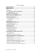
Table of Contents TABLE OF FIGURES .......................................................................................................8 INTRODUCTION..............................................................................................................9 MODEL OVERVIEW.....................................................................................................10 Models ..........................................................................................................................
WINDOWS PRINTER DRIVER ...................................................................................58 Windows 2000 Driver Installation............................................................................... 58 Windows XP Driver Installation.................................................................................. 62 Windows NT/9x Driver Installation.............................................................................
TABLE OF FIGURES Figure 1 – Model and Serial Number Location........................................................................10 Figure 2 – Traditional Printing...............................................................................................12 Figure 3 – Legacy Data stream Interpretation..........................................................................13 Figure 4 – Shipped with Printer .............................................................................................
INTRODUCTION The Fastmark 602 and Fastmark 603 are high-performance, low-cost Direct Thermal/Thermal Transfer labeling printers featuring the PALTM Print and Program language. PALTM Print and Program language is an interpretive page description language that allows printers to move beyond the role of normal printers.
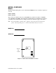
MODEL OVERVIEW Models The PALTM Print and Program versions of the Fastmark FM600 series are currently comprised of 2 models: FM602 (200DPI) FM603 (300 DPI) These models are similar in many ways. The FM602 has a print head resolution of 200 DPI versus 300 DPI on the FM603. Throughout this manual instructions and illustrations applying to a particular model will be labeled accordingly otherwise the instructions apply to all models.
Model Features For detailed feature specifications, please refer to Appendix A. Below is a brief summary of printer features: Standard Features q PALTM Print and Program Language . The PALTM Print and Programming Language is a powerful printer language combining both exceptional printing abilities with flexible programming abilities.
PALTM PRINT AND PROGRAM OVERVIEW Printers featuring PALTM Print and Program ability can be used in several ways in any given environment. This section describes 3 common ways this advanced capability is used. Details of how to take advantage of this advanced ability can be found in the PALTM Print and Program Reference Manual. For help and assistance determining the best way to use this ability in your situation, please consult your sales representative.
Legacy Data Stream Interpretation PALTM Print and Program capable printers uniquely address applications where upgrading to modern cost effective technology is desired. Often cost-prohibitive software reprogramming to change a data stream prevents an organization from moving to new printing technologies. Using a PALTM Print and Program capable printer solves this problem. In this case a PALTM program is written which interprets a data stream normally sent to the legacy device being replaced.
UNPACKING AND INSPECTION This section is provided to assist you in removing the printer from the shipping container and setting it up in the application environment. Inspect the shipping carton and contact the carrier directly to report any suspected damage. 1. With the shipping container in the upright position, remove the top foam packing piece. 2. Carefully, lift the printer straight up out of the box. 3. Remove the printer from the plastic bag and place the printer on a flat stable surface. 4.
INSTALLATION AND CONFIGURATION Finding a Location for the Printer Determine a suitable location for the printer and power supply brick with the following requirements: • Find a flat stable surface with sufficient clearance to allow for interface cables and media loading. • The location should be near the host or terminal. Consider the distance between the host and printer for the communication cable (serial or parallel cable).
Printer Parts and Features Top Cover External Media Slot Power Switch Media Out Slot Serial Port Cover Lock Parallel Port AC Power Port Figure 5 – External Switches, Indicators and Connections Top Cover Media Holder Thermal Printhead Ribbon Supply Holder Media Guides Media Sensor Media Present Bar Ribbon Take-up Holder Platen Roller Figure 6 – Internal Features Fastmark 600 Series User's Guide 16
Connecting the Power Cord 1. Make sure that the source voltage matches the input voltage of the power adapter. Caution: Incorrect source voltage could cause damage to the printer and/or the power adapter. 2. Ensure the printer power switch is Off, “O”. 3. Connect the power plug on the back of the printer. 4. Connect AC power plug to a suitable AC source. 5. Connect either a Centronics Parallel or RS-232 Cable.
Connecting the Printer to Your Host 1. You can connect the printer with any standard Centronics cable to the parallel port of the host computer or network print server. 2. Alternatively, you can connect the printer with a serial cable to the RS-232C port of your computer or terminal. (For PC compatibles, the RS-232C port is COM1, COM2 or COM3.) Parallel Port Serial Port Figure 8 – Communication Cable 3. If you use the serial port with your own cable, refer to the Appendix B and check the pin connection.
Loading the Ribbon Thermal Transfer Media only If Direct Thermal Media is used, skip to the section Loading Media. 1. Open the Top Media Access Cover by pressing in on both Cover locks (one on each side of the printer) and lifting the top cover until it rests in the vertical position. Cover Lock Figure 9 – Top Media Cover Latches 2. Press down on the two Print Head Latches to unlock the print head module .
3. Rotate the Print Head Module to the vertical position. 4. Verify that the Ribbon Supply Core and the Ribbon Take-up Core have two slots on the left side of the core 180-degree’s apart. If the width of the ribbon is less than the minimum core width or if no slots are present, insert one of the supplied Ribbon Core Adapters into each ribbon core. 5. The Slots in the Ribbon Core should mate to the Notches in the Left Ribbon Supply Holder and the Left Take-Up Holder.
6. Unwrap the Ribbon Supply Roll and prepare to place it into the Supply Holder area of the print head module. Make sure that the Ribbon is coming off the Top of the Ribbon Roll and to the front of the printer (Ribbon should be a wound-in type). See Supply Ribbon Installation figure below. 7. Insert the Ribbon Supply Core into the Ribbon Supply Area by first compressing the right side spring and snapping the left side of supply core into the left side of the notched wheel.
8. Loop the ribbon over the Print Head Module. Insert the Take-up Core into the Take-Up Area by first compressing the right side spring and snapping the left side of take-up core into the left side of the notched wheel. Make sure that the slots in left side of the core mate with the notches on the left side ribbon drive wheel. Take-Up Core Ink Side of the Ribbon Print Head Module Figure 13 – Ribbon Take-Up Installation 9.
10. Close and latch the print head module . Be sure to press firmly on both sides so that both latches clink into place. If either latch is not clicked into place it will cause the media to not feed properly or light print. Left Latch Right Latch Figure 15 – Print head Module Closed Note: The printer must be set to the Thermal Transfer mode to ensure the end of ribbon is detected. Refer to the section Feature Management Mode for instructions on how to change the Media Type feature.
Loading Media 1. Open the Top Media Access Cover by pressing in on both Cover locks (one on each side of the printer) and lifting the top cover until it rests in the vertical position. Cover Lock Figure 16 – Top Media Cover Latches 2. Spread the Media Holders apart and install the Media Roll onto the Media Roll Holder. The Media Holders are spring loaded thus keeping the media centered into the printer. Note 1: If the Media Core is 3 inches in diameter, insert the Media Core Adapter into the media core.
3. Press down on the two Print Head Latches to unlock the print head module . Print Head Module Print Head Release Latch Print Head Release Latch Figure 18 – Print Head Latches 4. Rotate the Print Head Module to the vertical position. Media Guides Print Head Module Media Sensor Platen Roller Figure 19 – Media Sensor and Guides 5. Spread the Media Guides to their full open position.
6. With the printing side up, feed the Media off the Media Roll under the Print Head Module and over the platen. Figure 20 – Loading Media over Platen Roller 7. Position the Media Sensor to the desired location. To position the Media Sensor examine the back of the Media Stock. As the media is pulled through the printer position the sensor to avoid holes or preprinted information on the back of the stock. These may cause incorrect top of form alignment.
If the printer has the Peeler or Cutter option go to either the Loading Media into the Peeler or Loading Media into the Cutter. 9. Close and latch the print head module . Be sure to press firmly on both sides so that both latches clink into place. If either latch is not clicked into place it will cause the media to not feed properly or light print. Left Latch Right Latch Figure 22 – Print head Module Closed 10. Close the Top Media Cover. 11.
Loading Media into the Peeler 1. Install media as indicated in the Loading Media Section. Return to these steps when directed to do so. 2. Remove about the first 6 inches of Labels from the media Backing. Figure 23 – Label Removal for Peeler Option 3. Make sure the leading edge of the Media Backing has a straight edge. 4. Pull down the Peeler Latch.
5. Position the Media Backing out of the printer and over the Peel Bar. Label Media Stock from Media Roll Backing Peeler Bar Peeler Roller Platen Roller Figure 25 – Feeding into the Peeler Mechanism 6. Push the Media Backing in the slot just under the Peel Bar and between the front cover. Continue to push the stock until it comes out of the larger slot in the front cover. Figure 26 – Backing Exit Position 7. If the Media Backing will not push through, then Press the Feed button one time.
8. Once the media comes out of the larger slot, gently roll the excess media back onto the Media Roll until the Backing is snug around the Peel Bar. 9. In this position the Media Backing coming out of the large slot in the front cover should be aligned with the Labels coming out of the printer. Note: If not, then pull down the Peeler Latch and gently pull the backing until they are aligned. Make sure to close the Peeler Latch when done. 10.
Loading Media into the Cutter Option 1. Install media as indicated in the Loading Media Section. Return to these steps when directed to do so. 2. Push the Media Stock through the slot on the Cutter Module near the platen Roller. Figure 28 – Inserting Labels in the Cutter Option 13. Close and lock the print head module by pressing firmly until the right and left Print Head Latches snap shut. 14. Close the Media Access Cover. 15. Press the Feed Button to cut the first label.
Calibrating Media Sensors Important: The first time media is installed, the Media Sensor must be calibrated. After the first calibration no further calibration is required unless the media type (length, color, backing material, etc.) is changed or irregular feeding occurs. 1. Ensure the printer is powered off. 2. Verify that the media is properly loaded and routed as detailed in Loading Media section. 3. Verify the Media Sensor is properly positioned directly over the object to be sensed (gap, hole, notch).
Printing the Configuration Label 1. Ensure the printer is powered off. 2. Make sure that Media width of 4 inches is installed and that the MEDIA WIDTH feature is set for 4.00 inches. 3. Verify that the media is properly loaded and routed as detailed in Loading Media Section. 4. While pressing and holding the FEED key, power on the printer. 5. When the printer begins to print the configuration label you may release the FEED key.
KEYPAD OPERATION The Front Panel keys serve multiple functions. Refer to the following tables for their specific functions. FEED PAUSE CANCEL £ READY £ MEDIA £ RIBBON Figure 32 – Fastmark 600 Series Front Panel LED Description m LED READY m MEDIA m RIBBON Fastmark 600 Series User's Guide Function ON: Printer is online OFF: Printer is either off line or in setup mode Steady Blinking: System error occurred.
Power up key functions The table below indicates the function performed when a key is pressed and held while the printer is powered up. Key FEED Function The printer generates a configuration label. See Printing the Configuration Label for details. PAUSE The printer performs a Calibration test. Media Sensor for details. CANCEL Pressing this key bypasses any PALTM program that is loaded into the printer and places the printer in its normal mode.
Feature Management Mode Feature Management Mode (FeatureMan) is a PC based program that directly interfaces with the printer on the PC’s serial port. All of the printer’s features are easily accessible and can be configured using the FeatureMan. While in FeatureMan mode the user can use either the mouse pointer on the PC or the three Keys on the printer to travel through the feature menus.
7. Click the Display Up/Down buttons to enter the setup mode. 8. Continue to click the Display Up/Down buttons as needed until the feature to be modified is displayed on the top line of the display. (ex. Baud Rate) Figure 34 – Changing Features 9. Click the Enter button to enter the Change mode. The top line of the display should start blinking to indicate the Change mode is active. 10. Click the Display Up/Down buttons as needed to select the new value. 11.
Setup Feature and Value List FEATURE NAME VALUE RANGE DESCRIPTION Media Type [ Direct Thermal, Thermal Transfer ] Set to Thermal Transfer if ribbon is used. Media Sensing [Gap, Continuous, Black Bar ] Set to match media sensing method. Calibrate Media (Form Length / Gap Length) automatically displayed and are not adjustable from this feature. Click the Enter button to initiate the media calibration. The detected media length and Gap are displayed.
Setup Feature and Value List (continued) Vert Print Align [ -0.50 - +0.50 ] (Inches) Adjust to move printed image up or down on label. Positive values move image up. Negative values move image down. After setting this feature the printer will feed to the top of the next label. Horz Print Align [ 0.00 - 1.00 ] (Inches) Adjust to move printed image left or right. Larger values move the image to the right. Vert Size Adjust [ -60 - + 60 ] Vertically expands or compresses print image.
Setup Feature and Value List (continued) Emulation Mode [ PAL, ASCII, Hex, Display ] Selects active emulation. ASCII emulation is a text emulation. Hex emulation is used for printing data in a hexadecimal format that shows the exact data being received by the printer. Display emulation is similar to the HEX emulation but print is in ASCII format. All control codes are printed as super/subscript characters. PAL emulation is the native language of the printer.
PALTM PRINT LANGUAGE INTRODUCTION This section provides an introduction to basic PALTM print language abilities including fonts and bar codes. For information regarding PALTM programming abilities, creating stand-alone applications, and other advanced topics please refer to the Fastmark PALTM Print and Program Reference Manual. The Windows driver included with the printer is an excellent method to generate PALTM print sequence based commands.
Smooth Scalable Fonts PALTM Print and Program capable printers allow a font to be selected by name, scaled, rotated, and placed on the drawing service. The table below lists the unique names used to select the fonts and a print sample showing a specific point size. Please refer to the PALTM Print and Program Reference manual for detailed information on the use of fonts.
UPC-A /UPCA UPC-E /UPCE EAN-8 /EAN8 EAN-13 /EAN13 Codabar /Codabar Postnet /Postnet Maxicode /Maxicode MSI Plessy /MSI PDF-417 /PDF417 Table 2 – PALTM Bar Code List and Samples Fastmark 600 Series User's Guide 43
PAL TM Print and Program Label Tutorial This Label Tutorial provides instructional steps showing the basic commands needed to create labels using PALTM Print and Programming Language. This section covers some of the most common sequences used to print fonts, bar codes, lines etc. Each label introduces a basic concept and builds on the preceding label. Upon completion of the tutorial, a label consisting of text in two orientations, a line, a box and a bar code will be covered.
Printing Text on a Label Label Output PALTM Command Sequences /Sans12.00pt findfont 12 scalefont setfont 72 72 moveto (Hello World!) show 1 _showpages Hello World! 1" 1" Purpose: Demonstrate how to print simple text on a label. findfont - Establish the font to use The fontname is preceded by a “/”. In this example, a Sans Serif 12 point font was chosen. See Table 1 for supported fonts. scalefont – Scale the selected font’s size in points It is typical to use the value indicated in the selected font.
PAL TM Print and Program Coordinate System The default coordinate system used by PALTM Print and Program Language is a traditional Cartesian coordinate system with the origin at the lower left-hand corner of the drawing surface: y (0,0) x PAL Coordinate System An internal “cursor” is maintained by PALTM that keeps track of where to put the next print object, i.e. text or lines, etc. At power up this internal cursor is set to the origin or (0,0).
Printing a Line PALTM Command Sequences Label Output Hello World! 1" /Sans12.00pt findfont 12 scalefont setfont 72 72 moveto (Hello World!) show 72 68 moveto 144 68 lineto stroke 1 _showpages 1" Purpose: Demonstrate drawing lines on a label. This example underlines the “Hello World!” text from the previous example.
Printing a Box Label Output Hello World! 1" 1" PALTM Command Sequences /Sans12.00pt findfont 12 scalefont setfont 72 72 moveto (Hello World!) show 72 68 moveto 144 68 lineto 30 30 moveto 258 30 lineto 258 258 lineto 30 258 lineto closepath 2 setlinewidth stroke 1 _showpages Purpose: Demonstrate the drawing of a rectangular box. This example builds on the previous example by drawing a frame around the label. A 4” x 4” (288 points x 288 points) label is used in this example.
Rotate a Text Object Hello World! Label Output Hello World! 1" 1" PALTM Command Sequences /Sans12.00pt findfont 12 scalefont setfont 72 72 moveto (Hello World!) show 72 68 moveto 144 68 lineto 30 30 moveto 258 30 lineto 258 258 lineto 30 258 lineto closepath stroke 72 90 moveto 90 rotate (Hello World!) show -90 rotate 1 _showpages Purpose: Demonstrate how to rotate text. This example builds on the previous example by placing another instance of “Hello World!” rotated 90 degrees.
Printing a Bar Code PALTM Command Sequence Hello World! Label Output *BARCODE123* Hello World! 1" 1" /Sans12.00pt findfont 12 scalefont setfont 72 72 moveto (Hello World!) show 72 68 moveto 144 68 lineto 30 30 moveto 258 30 lineto 258 258 lineto 30 258 lineto closepath stroke 72 90 moveto 90 rotate (Hello World!) show -90 rotate 100 100 moveto (BARCODE123) /Code39 _barcode 1 _showpages Purpose: Demonstrate how to print a bar code.
INTRODUCTION TO PALTM ADVANCED TOPICS Advanced Overview As previously mentioned the PALTM Print and Program Language is both a powerful printing and programming language. For example the included Windows driver takes advantage of the powerful printing portion of the language. Your VAR or internal programming staff may take advantage of some of the programming abilities. The fact that a single printer language supports both capabilities is unique.
PAL TM Print and Program Language Features q Page Description Language q No control Codes (easy to pass through networks, filters, etc.) q Compatible with midrange and mainframe computers and any host or PC programming language.
Sample Demo Files Several text files containing PALTM examples are included on the product CD. These files show programming techniques and examples, which may be incorporated into host or PC programming or used as reference. Each text file includes descriptive comments within the file. Below is a description of each file: File Name Description Pal_Procs_and_Formats.txt This file contains a number of print utilities written as PALTM procedures.
Example of a Procedure defined in PAL TM The following procedure is defined in Pal_Procs_and_Formats.txt and illustrates how PAL TM commands may be combined in a procedure to create a completely new function or capability. The file Pal_Procs_and_Formats.txt must be copied to the printer prior to using any of these utilities. The following utility shows how PALTM operators are used to create a simple Box draw procedure. This Box procedure makes use of another procedure defined called inchtopts.
Demo Label showing use of Print Utility Procedures After the file Pal_Procs_and_Formats.txt has been copied to the printer, a number of new procedures are now defined in the printer (until powered off). These procedures have been written specifically to demonstrate how to use the PALTM Print and Program operators to produce printed output. These procedures also provide easy ways to print various objects without actually needing to know the PALTM language.
Example of How to Define Label Formats The example below shows how a label format can be defined as a PALTM procedure. This label format called Mailing_Label uses 5 variables. Notice how the variables are defined in reverse order compared to how this format is called. This format is defined in Pal_Procs_and_Formats.txt. Looking at this file will also reveal that this procedure makes use of the print utility procedures also defined in this file.
Example of calling Label Format from Host Application The example below shows how a form named Mailing_Label that was defined in the file Pal_Procs_and_Formats.txt may be called from a host or PC application. The file Pal_Procs_and_Formats.txt must be copied to the printer first before the label format is defined. Also it is possible to store the formats in Flash memory which is an advanced topic not covered here. Other examples of calling these formats may be found in Format_Demo.
WINDOWS PRINTER DRIVER Windows 2000 Driver Installation 1. From the task bar select Start->Settings->Printers. The printer’s folder should be displayed. 2. Double click the Add Printer icon. q The Add Printer Wizard dialog should be displayed. q Click the Next button. 3. Select the Local printer option and click the Next button. 4. Select the desired printer port and click the Next button. 5. From the Manufacturers list dialog click the Have Disk button. 6.
Selecting Printer Fonts When the driver is installed, a custom TrueType font is also installed called AMT Sans Serif, which closely matches the resident scalable font in the printer. This font may be printed in a variety of point sizes. Using this font increases print speed and minimizes the data transmitted to the printer. Use of other True Type fonts are supported but are printed as graphics. To use the printer resident font: 1) For each size font highlight the font using the mouse.
Printing Bar Codes From Windows 2000 Applications Using the Fastmark PALTM Windows driver, printing bar codes from any Windows application is possible. These bar codes are printed using the internal bar code ability of the printer resulting in superior bar code quality. The following steps indicate how to do this: 1) Ensure the Fastmark PALTM Driver is selected within this application. 2) Select the media size to be used for this label.
Adjusting the Windows 2000 Driver Bar Codes Using the method just described, any Windows application can produce bar codes using the Fastmark drivers. Simply selecting the font as a bar code font does this. The driver also provides ways to finely adjust the bar code printed. For example, human readable text may be enabled or disabled. The X dimension may be adjusted. Depending on the bar code type other parameters may be adjusted for example enabling or disabling a check digit.
Windows XP Driver Installation 1. Go to the Printers and Faxes folder. 2. In the Printer Tasks window double click the Add a Printer icon. The Add Printer Wizard dialog should be displayed. Click the Next button. 3. Select the Local printer option and click the Next button. 4. If the New Printer Detection dialog is displayed, click the Next button to install manually. 5. Select the desired printer port and click the Next button. 6. From the Manufacturers list dialog click the Have Disk button. 7.
Selecting Printer Fonts When the driver is installed, a custom True Type font is also installed called AMT Sans Serif which closely matches the resident scalable font in the printer. This font may be printed in a variety of point sizes. Using this font increases print speed and minimizes the data transmitted to the printer. Use of other True Type fonts are supported but are printed as graphics. To use the printer resident font: 1) For each size font highlight the font using the mouse.
Printing Bar Codes From Windows XP Applications Using the Fastmark PALTM Windows driver, printing bar codes from any Windows application is possible. These bar codes are printed using the internal bar code ability of the printer resulting in superior bar code quality. The following steps indicate how to do this: 1) Ensure the Fastmark PALTM Driver is selected within this application. 2) Select the media size to be used for this label.
Adjusting the Windows XP Driver Bar Codes Using the method just described, any Windows application can produce bar codes using the Fastmark drivers. Simply selecting the font as a bar code font does this. The driver also provides ways to finely adjust the bar code printed. For example, human readable text may be enabled or disabled. The X dimension may be adjusted. Depending on the bar code type other parameters may be adjusted for example enabling or disabling a check digit.
Windows NT/9x Driver Installation 1. Go to the Printers and Faxes folder. 2. Double click the Add Printer icon. The Add Printer Wizard dialog should be displayed. Click the Next button. 3. Select the Local printer option and click the Next button. 4. Select the desired printer port and click the Next button. 5. From the Manufacturers list dialog click the Have Disk button. 6. From the Install From Disk dialog browse to the location of the driver files and click OK. 7.
Selecting Printer Fonts The driver has a resident font called AMT Sans Serif which is displayed in the application’s font list. This font may be printed in a variety of point sizes. Using this font increases print speed and minimizes the data transmitted to the printer. Use of True Type fonts are supported but are printed as graphics. To use the printer resident font: 1) For each size font highlight the font using the mouse. 2) From your applications font selection list, select AMT Sans Serif font.
Printing Bar Codes From Windows NT/9x Applications Using the Fastmark PALTM Windows driver, printing bar codes from any Windows application is possible. These bar codes are printed using the internal bar code ability of the printer resulting in superior bar code quality. The following steps indicate how to do this: 1) Ensure the Fastmark PALTM Driver is selected within this application. 2) Select the media size to be used for this label.
Adjusting the Windows NT/9x Driver Bar Codes Using the method just described, any Windows application can produce bar codes using the Fastmark drivers. Simply selecting the font as a bar code font does this. The driver also provides ways to finely adjust the bar code printed. For example, human readable text may be enabled or disabled. The X dimension may be adjusted. Depending on the bar code type other parameters may be adjusted for example enabling or disabling a check digit.
Using the Windows Driver To Produce PAL TM Print Command Examples To use the Windows driver to produce a PALTM sample for use in host programming do the following: 1) Design the label as needed using suitable Windows application. 2) Where possible always use the printer resident font such as AMT Sans Serif. 3) Use bar code fonts for data fields to be printed as bar codes. Use the driver Advanced Properties dialog box to select various options for the bar codes to be printed.
TROUBLESHOOTING AND MAINTENANCE The printer can detect and buy using the Feature Management Program (FeatureMan) display the following errors. In each case the Ready, Media, or Ribbon LED will blink steady. Printer Detected Errors ERROR MESSAGE DESCRIPTION RECOVERY Error: Power Fail The printer has detected +24VDC has dropped below a minimum acceptable level causing the printer to back up all settings to EEPROM. Turn printer off, wait 5 seconds and turn back on.
Printer Detected Errors (Continued) Error: Image System Error reported by the imaging subsystem indicating a memory shortage or other graphics problem. Press the FEED key to remove current print job. Cycle power on the printer. Verify communications settings are correct. Resend the print job. Error: Data Format The printer has detected a data format or parity error on the serial port.
Other User Detected Errors The following issues may be detected by the user but may not reported by the printer to the Feature Management Mode. Description of Issue No power or LEDs are not on Media not feeding properly Media is drifting to the right as it comes out of the printer. Possible Problem Printer not attached to a power source. Possible Correcting Procedures 1. Verify Power Plug on back of printer is pushed firmly in. 2. Verify Power Adapter is connected to a known power source. 3.
Description of Issue LEDs indicate Media Out Possible Problem Media Latches not closed. Or Media is too far from the Media Sensor to be detected. 2. Press firmly on the top of the Printhead Mechanism and verify the both the right and left latches are locked. 3. Close the Top Cover. Media Guide not in the proper position. 1. Verify Media is installed under the media guides. 2. Verify that the right Media Guide is in the proper Position. The media needs to be snug between the left and right guides.
Description of Issue Printer prints a label then continually feed labels through the printer. No print on Label Possible Problem Media is not Calibrated Possible Correcting Procedures Run Media Calibration procedure Media Sensor not functioning 3. Turn off the printer and remove the media. 4. Using a Swab dipped in Alcohol clean the Media Sensor. See User’s Manual for location of sensor. Spacing between labels is incorrect or does not exist. Verify that the stock matches that of previous roll.
Poor Print Quality Verify Media stock 1. Change Media with Stock from another unopened box. 2. Verify that Stock is Direct Thermal material. Verify Printhead Latches are closed. 1. Open Top cover 2. Press firmly on the Printhead Mechanism and verify that the right and left latches are locked. Other Possible Solutions q Verify type of media and ribbon are compatible. q Verify ribbon is not being used with direct thermal media. q Lower the print speed and adjust print darkness.
Peel and Present Sensing Description of Issue Printer prints multiple labels before pausing Printer does not Retract the label after it is taken. Printer Retracts media only after top cover is lifted. Does not print the next label Possible Problem Top Cover is not closed. Possible Correcting Procedures Close Top Cover. Sensor is not working properly 1. Clean Present Sensor 2. Recalibrate the Present Sensor. See Maintenance Manual for procedure. Printed label has been removed. 1.
Preventive Maintenance Before performing any Preventive Maintenance be sure to turn off the printer's power and unplug the power cable. Cleaning the Thermal Print Head (TPH) It is recommended at a minimum that the Print Head should be cleaned: • Each time a Ribbon is changed. • Each time a new roll of media is installed. 1. Turn off the printer, open the top cover, and if installed remove the ribbon. 2. Lift the print head module to the vertical position. 3.
Cleaning the Platen Roller It is recommended that the platen roller should be cleaned when: • Excessive dusty condition exists. • Following a media jam where the adhesive comes in contact with it. • Because of the squeezing process of feeding the media the roller can become sticky from the adhesive being pressed out from behind the label. 1. Turn off the printer and open the top cover. 2. Lift the print head module to the vertical position. 3.
Cleaning the Paper Compartment It is recommended that the Paper Compartment be cleaned regularly if exposed to a dust environment. This will keep dirt and dust from contaminating or damaging your printer (Print Head and Platen). 1. Turn off the printer and open the top cover. 2. Remove paper dust by blowing using compressed air or vacuuming. 3. Clean the paper compartment with cotton, which has been moistened with mild detergent.
Appendix A: GENERAL SPECIFICATIONS Specification Fastmark 602 PAL Print method Resolution Maximum print width Maximum print length Maximum print speed Onboard Memory Fastmark 603 PAL Direct Thermal or Thermal Transfer 203 dpi 300 dpi 4 inches 0.4 to 80 inches 0.
Appendix B: INTERFACE SPECIFICATIONS This appendix presents the serial and parallel interface specifications. These specifications include pin assignments, protocols and detailed information about how to properly interface your printer with your host or terminal. Serial Interface Pin Configuration The RS-232 serial interface uses a female, DB-9 conncetor.
Parallel (Centronics) Interface The parallel port uses a standard 36-pin Centronics connector.
Appendix C: ASCII TABLE The following table may be used to determine HEX values of ASCII characters. For example the character A is hex 41 commonly shown as 0x41H.
Appendix D: SELF TEST PRINT SAMPLE Fastmark 600 Series User's Guide 85
Appendix E: HIDDEN SETUP FEATURES To access the hidden list of features, select the Firmware Rev. feature then click the Enter button twice. The hidden feature list is now enabled and may be selected by clicking the Display Down button. Hidden Setup Feature and Value List FEATURE NAME VALUE RANGE DESCRIPTION Ripple Pattern N/A Click the Enter button to initiate a rolling ASCII ripple pattern. Factory Defaults N/A Clicking the Enter button resets all keypad features to factory defaults.
Appendix F: UPDATING PRINTER FIRMWARE Occasionally there may be a need to update printer firmware either to enhance capabilities or correct issues. Updating firmware via the parallel interface is possible only after activating the printers boot mode firmware. Use the following procedure to activate the boot mode firmware: 1) Enable the Feature Management mode. (Refer to the section Feature Management Mode section for instructions.) 2) Enable the Hidden Setup Features. (Refer to Appendix E for instructions.
7) In the FlashWiz Lite section, select the appropriate LPT port to be used for the download. 8) Click the File button to select the appropriate download file. 9) Click the Send button to start the download. 10) After the download is complete follow the instructions on the display of the FeatureMan program to reset all printer features. At this point you can either continue operating the printer in the Feature Management Mode or you can exit.
Boot Mode Feature and Value List The Boot Mode has several programmable features that are used during firmware updates. Click the Display Up/Down buttons to access the Boot mode features. FEATURE NAME Download New F/W VALUE RANGE N/A DESCRIPTION Click the Enter button to start download mode. The display will change to: Download New F/W Waiting For Data / The printer will wait on a firmware update file on the Parallel ports.