Fastmark M1/203dpi Direct Thermal Barcode Printer User’s Guide 0 Document #120103 A
Contents Copyright Declaration................................................................................................... i 1. Introduction ............................................................................................................... i 1.1 Product Introduction ....................................................................................................................... i 1.2 Compliances .......................................................................................
Copyright Declaration Information in this subject to change without notice and does not represent a commitment on the part of AMT Datasouth Corporation. No part of this manual may be reproduced or transmitted in any form by any means, for any purpose other than the purchaser’s personal use, without the expressed written permission of AMT Datasouth Corporation. 1. Introduction 1.1 Product Introduction Thank you for purchasing the Fastmark M1 bar code printer.
CAUTION 1. HAZARDOUS MOVING PARTS IN CUTTER MODULE. KEEP FINGER AND OTHER BODY PARTS AWAY. 2. THE MAIN BOARD INCLUDES REAL TIME CLOCK FEATURE HAS LITHIUM BATTERY CR2032 INSTALLED. RISK OF EXPLOSION IF BATTERY IS REPLACED BY AN INCORRECT TYPE. 3. DISPOSE OF USED BATTERIES ACCORDING TO THE MANUFACTURER INSTRUCTIONS. WARNUNG! GEFÄHRLICHE BEWEGLICHE TEILE – FINGER UND ANDERE KÖRPERTEILE FERNHALTEN! VORSICHT! EXPLOSIONSGEFAHR BEI ERSATZ DER BATTERIE DURCH UNZULÄSSIGEN TYP.
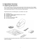
2. Operations Overview 2.1 Unpacking and Inspection The Fastmark M1 printer has been specially packaged to withstand damage during shipping. Please carefully inspect the packaging and printer upon receiving the bar code printer. Please retain the packaging materials in case you need to reship the printer. Unpacking the printer, the following items are included in the carton.
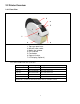
2.2 Printer Overview 2.2.1 Front View 3 4 5 7 1 2 6 1. Top cover open lever 2. MicroSD card socket 3. Media view window 4. LED indicator 5. Feed button 6. Paper exit chute 7. LCD display (Optional) * Recommended MicroSD card specification. SD card spec SD card capacity Approved SD card manufacturer V1.0, V1.1 MicroSD 128 MB Transcend, Panasonic V1.0, V1.1 MicroSD 256 MB Transcend, Panasonic V1.0, V1.1 MicroSD 512 MB Transcend, Panasonic V1.0, V1.1 MicroSD 1 GB Transcend, Panasonic V2.
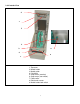
2.2.2 Interior View 4 1 5 2 3 9 8 6 7 1. Top cover 2. Media holder 3. Media guide 4. Printhead 5. Gap sensor (receiver) 6. Gap sensor (transmitter) 7. Platen roller 8. Black mark sensor 9.
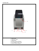
2.2.3 Rear View 5 6 1 3 2 4 1. Power switch 2. Power jack socket 3. USB interface 4. RS-232C interface (Optional) 5. Fan-fold paper entrance chute 6.
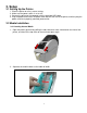
3. Setup 3.1 Setting Up the Printer 1. Place the printer on a flat, secure surface. 2. Make sure the power switch is set to “off”. 3. Connect the printer to the computer with the provided USB cable. 4. Plug the power cord into the AC power cord socket at the rear of the printer, and then plug the power cord into a properly grounded power outlet. 3.2 Media Installation 3.2.1 Loading Internal Media 1.
3. Place the roll between the holders and close them onto the core. Sensor Platen roller 4. Place the media, printing side face up, through the media guides, over media sensor and place the label leading edge onto the platen roller.
5. Close the top cover gently and make sure the cover latches securely. 6. Use “Diagnostic Tool” to set the media sensor type and calibrate the selected sensor. (Start the “Diagnostic tool” Select the “Printer Configuration” tab Click the “Calibrate Sensor” button) Note: Please calibrate the gap/black mark sensor when changing media.
3.2.2 Loading External Media 1. Open the printer’s top cover and separate the media holders to fit the media width. 2. Press down the media holder lock switch to fix the media holder. 3. Feeds the media through the rear external label entrance chute. And place the paper, printing side face up, through the media guides, media sensor and place the label leading edge onto the platen roller. Rear external label entrance 4. Close the top cover gently. 5.
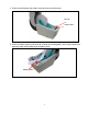
3.2.3 Loading Media in Peel-off Mode (Optional) 1. Refer to section 3.2.1 to load the media. 2. Open the top cover and peel-off panel after calibrated the sensor. Peel-off panel 3. Lead the media through the backing paper opening, beneath the peel-off roller.
4. Push the peel-off panel back to the printer. Label exits here Backing paper (Liner) 5. Close the top cover gently. 6. Press the FEED button to test. Note: Please calibrate the gap/black mark sensor when changing media.
3.2.4 Loading Media in Cutter Mode (Optional) 1. Refer to section 3.2.1 to load the media. 2. Lead the media through the cutter paper opening. Cutter paper opening 3. Close the top cover gently. 4. Use “Diagnostic Tool” to set the media sensor type and calibrate the selected sensor. (Start the “Diagnostic tool” Select the “Printer Configuration” tab Click the “Calibrate Sensor” button) Note: Please calibrate the gap/black mark sensor when changing media.
3.3 Diagnostic Tool The Diagnostic Utility is enclosed in the CD disk \Utilities directory. The Diagnostic Utility is a toolbox that allows users to explore the printer's settings and status; change printer settings; download graphics, fonts, and firmware; create printer bitmap fonts; and to send additional commands to the printer. Using this convenient tool, you can explore the printer status and settings and troubleshoot the printer. Note: This utility works with printer firmware V6.00 and later versions.
3.3.2 Printer Function (Calibration/setup) 1. Select the PC interface connected with bar code printer. 2. Click the “Function” button to setting. 3. The detail functions in the Printer Function Group are listed as below.
3.4 Setting Ethernet by Diagnostic Utility (Optional) The Diagnostic Utility is enclosed in the CD disk \Utilities directory. Users can use Diagnostic Tool to setup the Ethernet by USB and Ethernet interfaces. The following contents will instruct users how to configure the Ethernet by these interfaces. 3.4.1 Using USB interface to setup Ethernet interface 1. Connect the USB cable between the computer and the printer. 2. Turn on the printer power. 3.
3.4.2 Using Ethernet interface to setup Ethernet interface 1. Connect the computer and the printer to the LAN. 2. Turn on the printer power. 3. Start the Diagnostic Utility by double clicks on the icon. Note: This utility works with printer firmware V6.00 and later versions. 4. Select “Ethernet” as the interface then click on the “Setup” button to setup the IP address, subnet mask and gateway for the on board Ethernet. 5. Click the “Discover Device” button to explore the printers that exist on the network.
7. Click “Change IP Address” to configure the IP address obtained by DHCP or static. The default IP address is obtained by DHCP. To change the setting to static IP address, click “Static IP” radio button then enter the IP address, subnet mask and gateway. Click “Set IP” to take effect the settings. Users can also change the “Printer Name” by another model name in this fields then click “Set Printer Name” to take effect this change.
3.5 Install Micro SD Memory Card 1. Open the SD memory card cover located on the left side of the printer. 2. Insert the MicroSD card into the socket. 3. Close the memory card cover. * Recommended SD card specification. SD card spec SD card capacity Approved SD card manufacturer V1.0, V1.1 MicroSD 128 MB Transcend, Panasonic V1.0, V1.1 MicroSD 256 MB Transcend, Panasonic V1.0, V1.1 MicroSD 512 MB Transcend, Panasonic V1.0, V1.1 MicroSD 1 GB Transcend, Panasonic V2.
3.6 Mount the Printer on the Wall There are three holes in the bottom of printer. The printer can be mounted on the wall with 1/8” head screws. 1 ¾” 3 1/16” Note: Please hang properly to avoid breakage.
4. LED and Button Functions This printer has one button and one three-color LED indicator. By indicating the LED with different color and pressing the button, printer can feed labels, pause the printing job, select and calibrate the media sensor, print printer self-test report, reset printer to defaults (initialization). Please refer to the button operation below for different functions. 4.
Release 3. Printer initialization 4. Set black mark sensor as media sensor and calibrate the black mark sensor 5. Set gap sensor as media sensor and calibrate the gap sensor 6. Skip AUTO.BAS Release Release Release 4.3.1 Gap/Black Mark Sensor Calibration Gap/black mark sensor sensitivity should be calibrated at the following conditions: 1. A brand new printer 2. Change label stock. 3. Printer initialization. Please follow the steps below to calibrate the gap/black mark sensor. 1.
Self-test Printer will print the printer configuration after gap/black mark sensor calibration. Self-test printout can be used to check if there is any dot damage on the heater element, printer configurations and available memory space.
Hex decimal data related to left column of ASCII data ASCII Data Note: 1. Dump mode requires 2” wide paper width. 2. Turn off / on the power to resume printer for normal printing. 3. Press FEED button to back to the previous menu. 4.3.3 Printer Initialization Printer initialization is used to clear DRAM and restore printer settings to defaults. Printer initialization is activated by the following procedures. 1. Turn off the power switch. 2. Hold on the button then turn on the power switch. 3.
4.3.4 Set Media Black Mark Sensor and Calibrate Please follow the steps as below. 1. Turn off the power switch. 2. Hold on the button then turn on the power switch. 3. Release the button when LED turns green/amber after 5 green blinks. (Any green/amber will do during the 5 blinks). The LED color will be changed in the following order: Amber red (5 blinks) amber (5 blinks) green (5 blinks) green/amber (5 blinks) red/amber (5 blinks) solid green 4.3.
5. Troubleshooting The following guide lists the most common problems that may be encountered when operating this bar code printer. If the printer still does not function after all suggested solutions have been invoked, please contact the Customer Service Department of your purchased reseller or distributor for assistance. 5.1 LED Status This section lists the common problems that according to the LED status and other problems you may encounter when operating the printer. Also, it provides solutions.
5.2 Print Problem Problem Possible Cause Recovery Procedure Check if interface cable is well connected to the interface connector. Re-connect cable to interface. The serial port cable pin configuration is Please replace the cable with pin to pin not pin to pin connected. connected. Not Printing The serial port setting is not consistent between host and printer. Please reset the serial port setting. The port specified in the Windows driver Select the correct printer port in the is not correct.
5.3 LCD display This section lists the LCD display messages that you may encounter when operating the printer. Also, it provides solutions. Messages Possible Cause Recovery Procedure Head Open No Paper Paper Jam * The printer top cover is open. * Please close the top cover. * Running out of label. * The label is installed incorrectly. * Gap/black mark sensor is not calibrated. * Supply a new label roll. * Please refer to the steps in user’s manual to reinstall the label roll.
6. Maintenance This session presents the clean tools and methods to maintain your printer. 1. Please use one of following material to clean the printer. Cotton swab (Head cleaner pen) Lint-free cloth Vacuum / Blower brush 100% ethanol 2. The cleaning process is described as following: Printer Part Method Interval 1. Always turn off the printer before cleaning Clean the print head when changing a the print head. new label roll 2. Allow the print head to cool for a minimum of one minute. 3.
Corporate Headquarters Manufacturing/Service 803 Camarillo Springs Road, Suite-D Camarillo, CA 93012 TEL: 800.215.9192 FAX: 805.484.5282 Web site: www.AMTDatasouth.com 5033 Sirona Drive, Suite-800 Charlotte, NC 28273 TEL: 800.476.2120 FAX: 704.525.