
Product Manual
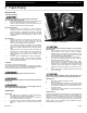
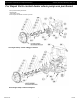
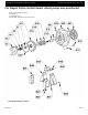
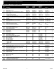
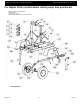
Table Of Contents

5585-250-00
1
11/2016
Specifications Information and Repair Parts Manual 5585-B6, 5585-D6, 5585-H6, & 5587-Y6
x
Please read and save this Repair Parts Manual. Read this manual and the General Operating Instructions carefully before attempting to assemble,
install, operate or maintain the product described. Protect yourself and others by observing all safety information. The Safety Instructions are contained
in the General Operating Instructions. Failure to comply with the safety instructions accompanying this product could result in personal injury and/or
property damage! Retain instructions for future reference. AMT reserves the right to discontinue any model or change specifications at any time without
incurring any obligation.
©2016 AMT Pump Company, A Subsidiary of The Gorman-Rupp Company, All Rights Reserved.
Periodic maintenance and inspection is required on all pumps to insure proper operation. Unit must be clear of debris and sediment. Inspect for leaks and loose bolts. Failure
to do so voids warranty.
6” Trash Pump
DESCRIPTION
This trash pump is heavy duty, centrifugal, engine driven, self-priming (to 20 ft. lift), and transportable unit. Pump is equipped with precision lapped
mechanical shaft seal to reduce the likelihood of leakage, and a clog resistant impeller capable of handling solids up to 3" in spherical diameter. Units
are used to handle water containing stones, sticks, mud, and other solids (up to 20% by volume). O-ring sealed flange connection to provide leak-free
low maintenance operation. Suction flange male NPT threaded for direct coupling to a standard NPS hose connector with rubber gasket. Liquid
temperature range is 40º to 180º F (4º to 82º C). Maximum casing pressure if used in a flooded suction application is 50 psi. For use with nonflammable
liquids that are compatible with pump component materials.
All models come equipped with a 12V electric starting system (battery
not included). A fully plumbed fuel tank is standard. Gas engine units
are equipped with a 12 gallon plastic tank and diesel engine units have
an 18 gallon aluminum tank. All units equipped with a digital
tachometer/hour meter.
Pump and engine are mounted on an easy maintenance sliding frame
assembly. Frame can be equipped with pneumatic tires, lighting
system, support jacks, and a 2" diameter ball mount tongue hitch. A
lunette ring is optional.
Tires, wheels, and lighting system meet DOT requirements and are
supplied with certificate of origin and serial number. Check state and
local requirements to register trailer/pump for highway towing.
SPECIFICATIONS
Suction Inlet…………………………………………………..6” NPT (male)
Discharge Outlet…………………………………….……….6” NPT (male)
Dimensions (overall)
Trailer Mounted…………………………………….……….9’L x 4’W x 5’H
Frame Mounted………………………………….……….6’L x 3’W x 3’3”H
Engine…………………5585-B6: 27 HP B&S Vanguard Discontinued
……………………………………………...5585-H6: 24HP Honda GX670
………….………………………….….5585-D6 27HP Daihatsu/Vanguard
…………………………………….5587-Y6: 23HP Yanmar 3TNM72-ASA
BASIC CONSTRUCTION
Cast aluminum with cast iron volute, stainless steel impeller, suction
flange and discharge manifold. Viton silicon carbide shaft seal, Buna
O-rings, Buna/Neoprene suction check valve.
UNPACKING
Refer to Repair Parts Illustration and Repair Parts List to aid in
identifying parts. Unpack and separate all pump components from
shipping/packaging materials, making sure all parts are accounted for.
Retain all manuals for reference.
Package should contain:
1. Pump and engine completely assembled and mounted to
frame.
2. Tongue packaged alone (not attached to frame).
3. Tail lights, side lights, wiring packaged alone.
4. Manuals included: Specifications information and repair
parts manual, Operating Instructions/maintenance manual,
tachometer/hour meter instructions, engine
instruction/owner’s manual.
ASSEMBLY
Trailer Mounted Pump
Tongue Assembly Instructions
1. Remove four mounting bolts and nuts inserted into tongue
mounting holes.
2. Position tongue under frame. Line up tongue mounting holes
with holes in frame front and middle cross members.
3. Secure tongue to frame by installing four (4) mounting bolts
and nuts. Torque to 15-18 ft. lbs.
Light Kit Assembly Instructions
1. Position wiring harness under tongue, "Y" branch of harness
should be under front tongue to frame connection.
2. Feed each branch wiring harness through hole in end of
frame cross member and support loops at fender mounting
bolts. Green/brown wire harness left side (looking from
tongue end to pump end) yellow/brown wire harness right
side. Pull harness snug (towards pump end of frame) while
keeping "Y" at tongue connection.
3. Remove support loops from tongue. Clip loops over plug
end of wire harness. Install loops back into position
supporting wire harness. Plug end should be free under
coupler end of tongue. Install grounding eye under screw
holding loop closest to tongue ball coupler.
4. Clip support loops over harness branches past "Y". Position
loops on exposed end of tongue mounting bolts. Secure with
a flange nut.
5. Install side lights onto frame side rails. Connect side light
wire (wire may be inside lens) with brown wire in each
branch harness. Secure connection with splice fitting or wire
nut.
6. Feed taillight wires through middle hole of three holes on
each end of pump end cross member.
7. Make taillight connections by pushing exposed stranded
wire into appropriate hole in rear of taillight. Make certain
taillight with license plate light is on the right side (looking
from tongue).
8. Clip a support loop over the end of each wire harness.
9. Install license plate holder on right taillight studs. Install both
taillight studs thru rear cross member holes. Position support
clip on outer taillight stud. Secure taillights with flange nuts.
Frame Mounted Pump:
1. Unit shipped fully assembled.
NOTE: Follow all recommendations in General Operating Instruction
and Maintenance Manual provided with this pump. In addition, follow
the specific recommendations that follow.