
Product Manual
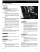
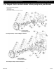
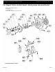
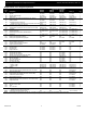
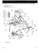
Table Of Contents

5585-250-00
2
11/2016
Specifications Information and Repair Parts Manual 5585-B6, 5585-D6, 5585-H6, & 5587-Y6
x
6” Trash Pump
Figure 1 – Fuel Valves
INSTALLATION
Trailer Mounted Pump
To avoid trailer tipping, set rear trailer stabilizer jacks before
removing trailer from vehicle hitch.
1. Always set trailer tongue stand and rear trailer stabilizer jacks
before unhooking trailer hitch from vehicle tow ball.
2. Make sure pump and trailer are level and trailer wheels are
blocked to prevent movement during operation.
Frame Mounted Pump
1. Pump frame must be supported on a level firm surface.
Anchoring pump frame to support surface is required to
prevent movement or tipping during operation. Mounting
holes are provided on bottom flange of frame side rails. Allow
sufficient clearance around pump frame to perform routine
maintenance.
All Installations:
1. Suction line should be as short and direct as possible, have a
constant slope up to the pump’s suction port, and line
diameter must match suction port diameter. Use only
reinforced non-collapsible hose on pump suction.
2. Check condition of suction hose gaskets before installation.
Weak, worn, leaking gaskets will allow an air leak at suction
connection. If suction connection leaks air, the pump will not
prime.
3. Supports must be used to carry the weight of the suction and
discharge lines. The pump should not be used to support the
entire weight of the suction and discharge lines.
Damage/breakage of pump ports may occur if lines are not
supported.
4. If a check valve or collapsible hose is used on discharge, a
means of venting air from the pump discharge manifold is
required during the priming cycle. If air cannot escape from
casing, the pump will not prime.
Lifting Bail
Pump frame is equipped with a lifting bail.
Lifting bail provides a convenient lifting point if positioning pump with a
crane or similar equipment is necessary. Bail and lifting bolt assembly
will support only the weight of frame/trailer, pump and driver.
Periodically re-torque lifting bolt assembly to 100 ft. lbs.
Remove suction and discharge lines and drain all liquid from pump
before lifting.
Lift pump assembly and trailer only. Do not load piping, hoses or
other equipment on trailer during lifting.
OPERATION
Starting Unit
1. Fill engine with oil according to engine manufacturer’s
specifications listed in engine manual supplied.
2. Fill fuel tank with appropriate fuel for engine. Do not fill tank to
the top allow at least an inch of airspace.
3. Fill pump casing with water through discharge manifold
priming port. Casing must be full of water or pump will not
prime.
Do not run pump dry as permanent damage to the mechanical
seal will result.
4. Open all valves in the fuel system, fuel tank, fuel filter, &
water separator. Valves may be closed for shipping.
Operating starter with valves closed may result in an air
locked fuel system. Consult engine manufacturer for remedy
to air locked fuel system. SEE FIGURE 1
5. Start the engine, following instructions in engine manual.
6. Run engine at full throttle during priming cycle. Tachometer
should indicate 3500 rpm or greater.
7. After pump has primed and is producing full flow, engine
speed should be regulated to produce desired pump
performance level. Under high lift and/or low discharge head
conditions, engine speed should be decreased to retard
cavitation. This will extend pump, seal, and engine service
life.
8. Yanmar diesel engine: Maximum operating speed, after full
prime, is 3200 rpm.
Do not operate pump unattended. Shaft seal damage will occur if
prime is lost or if flow is insufficient to keep the shaft seal cool.
Refueling Tank
1. Allow unit to cool before adding fuel to tank.
2. Remove tank cap.
3. Add fuel through fill neck. Watch fuel level gauge during
filling and stop adding fuel when the gauge indicates full. Do
not overfill tank, allow an inch or two of airspace from fuel
level to top of tank.
4. Install tank cap. Rotate clockwise until it hits internal stop
indicating that it is sealed.
Pump End Drain
Pump end is equipped with an NPT drain port. The port is located on
the pump adapter plate (Ref. No. C28) at the 6 o’clock position. The
elbow (Ref. No. C30) is installed in the port to direct the liquid down
through frame. The indented hex pipe plug (Ref. No. C31) is installed
in elbow. Use a 9/16" L-hex wrench to remove plug. A ball valve and
length of pipe or hose (not supplied) may be installed to direct the
drain liquid away from the pump.