
Product Manual
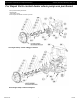
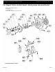
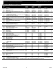
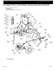
Table Of Contents

5585-250-00
4
11/2016
Specifications Information and Repair Parts Manual 5585-B6, 5585-D6, 5585-H6, & 5587-Y6
x
6” Trash Pump
MECHANICAL SEAL REPLACEMENT
NOTE: Always replace the mechanical seal parts (Ref. No. E6 & E7)
as an assembly (Ref. No. E5) to ensure proper mating of mechanical
components.
NOTE: Always inspect impeller stub shaft ball bearing (Ref. No. E14)
during seal replacement. The bearing may have been damaged by
leaking water. Refer to IMPELLER STUB SHAFT BEARING
REPLACEMENT section.
1. Access impeller/seal plate area as described in SLIDING
ENGINE SLED OPERATION section.
2. Unscrew impeller (Ref. No. E2) from the impeller stub shaft
(Ref. No. E15). Use a rubber mallet or soft block of wood and
hammer to loosen impeller. Remove any impeller shims (Ref.
No. E3), shaft sleeve and seal head (Ref. E6) from impeller
stub shaft.
3. Remove two 1/2-13x1" cap screws (Ref. No. E12) holding
seal plate (Ref. No. E11) to bearing housing (Ref. No. E17 or
E18). Remove seal plate from bearing housing.
4. Remove impeller shaft washer (Ref. No. E13) and inspect
impeller stub shaft ball bearing for water damage or wear.
Replace shaft washer with flat surface toward impeller.
5. Push seal seat from the seat plate recess with a screwdriver.
6. Clean the seal plate recess before inserting a new seal seat.
7. Carefully wipe the polished surface of the seal seat with a
clean cloth.
8. Wet the rubber portion of the seal seat with a light coating of
soapy water.
9. Press the new seal seat squarely into the cavity in the seal
plate. If the seal seat does not press squarely into the cavity,
it can be adjusted in place by pushing on it with a piece of
pipe. Always use a piece of cardboard between the pipe and
the seal seat to avoid scratching the seal seat. (This is a
lapped surface and must be handled very carefully).
10. After the seal seat is in place, ensure that it is clean and has
not been scratched or cracked.
11. Using a clean cloth, wipe the impeller stub shaft and make
certain that it is clean.
12. Install seal plate and secure to bearing housing adapter face
with two 1/2-13x1 cap screws.
13. Apply a light coating of soapy water to the inside rubber
portion of seal head and slide onto the shaft sleeve. Slip the
shaft sleeve and seal head onto the impeller stub shaft with
seal head lapped surface towards seal seat lapped surface.
14. Replace any impeller shims removed during disassembly.
15. Screw the impeller back in place tightening until it is seated
against shims and shaft sleeve.
NOTE: Make sure seal spring retainer is not pinched between
impeller/shims and end of shaft sleeve.
16. Refer to section entitled Shim Adjustment at this time if shaft
sleeve or any other parts listed therein have been replaced.
17. Check seal plate O-ring (Ref. No. C37), make sure it is not
damaged or worn and is in position on seal plate.
NOTE: Always inspect O-ring seals. Replace when cracked or worn.
Wet the O-ring with soapy water for ease of assembly.
18. Slide engine/sled back into position aligning lead diameter on
seal plate with adapter inside diameter. Replace three 1/2-
13x1-3/4 cap screws. Tighten six 1/2- 13 hex nuts clamping
sled to casing frame.
19. Remount any other parts and reconnect spark plug wires and
battery.
SHIM ADJUSTMENT
Manual Method:
1. When installing a replacement impeller, shaft sleeve, bearing
housing, seal plate, or volute (Ref. No. C24), it may be
necessary to vary the number of impeller shims that will be
required. This is done by adding one shim more than was
removed and reassembling the pump as described in
Mechanical Seal Replacement section.
2. Ensure that volute, adapter, seal plate and bearing housing
are fitted firmly. Check tightness of all fasteners.
3. Remove spark plug wires and bump engine over slightly with
electric starter. If engine does not turn freely or interference
between impeller and volute can be heard, disassemble
pump and remove one shim.
NOTE: When adding or removing shims, it is best to proceed with a
0.020" increment each time. If engine does turn freely, add shims until
it does strike, then remove a 0.020" shim. This will ensure maximum
performance.
4. Proper running clearance is 0.020" to 0.040"
5. Follow the above procedure until proper clearance is
obtained.
Measurement Method:
1. When installing a replacement impeller, shaft sleeve, bearing
adapter, seal plate or volute, it may be necessary to vary the
number of impeller shims that will be required. This can be
accomplished by measurement with a suitable size depth
micrometer or similar measuring instrument.
2. Measure depth from pump adapter-seal plate mounting
surface to impeller face of volute. Measurement should be
close to 5.960".
3. Add or remove impeller shims until height of impeller face to
seal plate pump adapter mounting surface measures 0.020"
to 0.040" shorter than depth measured in previous step.
4. Slide engine/sled back into position aligning lead diameter on
seal plate with adapter inside diameter. Replace three 1/2-
13x1-3/4 cap screws. Tighten six 1/2-13 hex nuts clamping
side rails to frame rails.
5. Remove spark plug wires and bump engine over slightly with
electric starter. If engine does not turn freely or interference
between impeller and volute can be heard, disassemble
pump and remove one shim. Rotate engine again. Engine
must rotate freely.
IMPELLER AND VOLUTE REPLACEMENT
Impeller and volute are subject to wear only by abrasive sand or
sediment laden liquids. If badly worn, all these parts can be replaced
and the pump thus restored to full efficiency.
NOTE: When the clearance between the impeller and the volute
exceeds 1/16" at the face of the impeller or 1/8" on the outside
diameter of the impeller, it may be necessary to take corrective action.
The increased clearance can cause lengthened priming times and
reduce pumping capacity. If both the priming and capacity of your unit
are satisfactory for your application, it is recommended that no
corrective maintenance be performed regardless of what clearances on
your unit may have developed, since the increased clearances in
themselves are not generally harmful to your pump. Normally, new
pump clearances can be restored by simply shimming behind the
impeller. If the impeller is badly worn, it is recommended that the
impeller be replaced. This is usually all that is required since only on
unusually abrasive services does the cast iron volute show
deterioration. Occasionally a stone or hard object might get caught in
the impeller and cause damage to the volute/cutwater. In these cases,
follow the instructions below for replacement.