Digital Series Power Supply Instruction Manual 855-317-000 2A Angas Street, Meadowbank NSW 2114 Sydney, Australia . Tel: +61-2-9809 5022 Fax: +61-2-9809 5077 e-mail: sales@amtex.com.au Web Site: www.amtex.com.
Rev 1.71 Dec 2013 Copyright © 2012 Innovative Circuit Technology Ltd. All rights reserved. No part of this publication may be reproduced, stored in a retrieval system or transmitted in any form or by any means, electronic, mechanical, photocopying, recording or otherwise, without the prior written consent of Innovative Circuit Technology Ltd.
Table of Contents 1. PRODUCT DESCRIPTION ...................................5 2. INSTALLATION ....................................................6 2.1. 2.2. 2.3. 2.4. 3.1. 3.2. 3.3. 3.4. 3.5. Control Panel Keys and Controls Setting the DC Output Control Panel Menus Control Panel Menu Password Reset Administrator Password / IP Address Reset 11 11 12 17 17 SMART PARALLEL OPERATION .....................18 4.1. RS485 Interface Connector 4.2. Configuring the Power Supplies for Parallel Operation 4.3.
WARNING! – IMPORTANT SAFETY NOTICES Risk of personal injury and property damage! You must exercise caution and follow the safety requirements listed below when using your Digital Series power supply.
1. PRODUCT DESCRIPTION ICT Digital Series DC power supplies provide high efficiency in a space-saving 1RU rack mount design with power factor corrected AC input and extremely low noise for powering wireless communications and broadband equipment where high reliability is essential. They have the ability to function either as a standalone DC power supply or for battery charging applications.
Model Watts (Max) Input VAC ICT1200-12S 1350 100-265 Model Watts (Max) Input VAC ICT1200-24S 1350 100-265 ICT1200-48S 1350 100-265 ICT600-12S 675 100-265 ICT600-24S 675 100-265 ICT600-48S 675 100-265 Output VDC Output Description (A) 12VDC 100A 11.5 - 15.5 100 Power Supply Output Output Description VDC (A) 24VDC 50A 23 - 31.0 50 Power Supply 48VDC 25A 47- 62.0 25 Power Supply 12VDC 50A 11.5 – 15.5 50 Power Supply 24VDC 25A 23 – 31.0 25 Power Supply 48VDC 12A 47 – 62.0 12.
2.2. Back-up Battery An external lead-acid battery with the same nominal voltage as the power supply may be connected directly in parallel with the output terminals, or to the BAT terminal (on units with the LVD option “B”) to provide a DC backup capability. Use appropriate wire, over current protection and disconnect device as outlined in the Installation section.
Note that during battery operation with AC power off the front panel display and optional external communication ports will not be powered. Only the battery LVD circuitry will be active. 2.3. Installation The ICT Digital Series Power Supply is designed to be used in an industry standard 1RU 19” rack mount cabinet or other restricted access location. Insert the unit at the desired rack location, and secure the unit using standard rack nuts and bolts (not provided).
WARNING! Battery current through the “BAT” terminal must not exceed the maximum current limit rating of the Digital Series power supply. Connect the “BAT” terminal to the external battery POSITIVE using a suitably rated over current protection and disconnect device. Otherwise damage to the unit, load, battery, and personal injury may occur if the battery is inadvertently connected in reverse polarity, or the output circuit is over loaded or shorted. 3.
Ensure unit is off and power is disconnected prior to making connections to the REMOTE connector terminals to avoid damaging the power supply or connected devices. • Connect external Remote Shutdown control lines (TTL compatible signal) to the REM SD+ (pin 1) and REM SD- (pin 2) terminals of the “REMOTE” connector on the back panel if external on/off control of the power supply output is required.
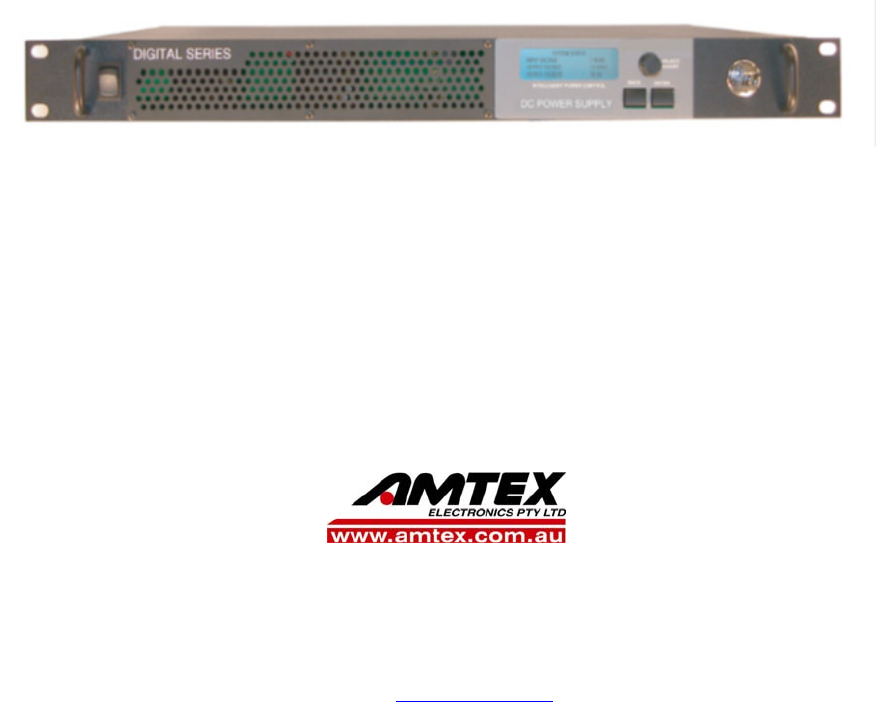
The Intelligent Power Control on the front of the Digital Series power supply allows you to view the status of the power supply, and modify the power supply settings. The Control Panel consists of the following: (Figure 2 Front Panel Display and Control) 3.1. Control Panel Keys and Controls Encoder Wheel: Turning the encoder wheel will scroll through the Control Panel screens and menu items. When modifying the value for a setting, turning the encoder wheel will increase or decrease the value.
To set the output voltage, current limit, and enable the output, do the following: 1. Install the power supply and connect the load as described in the Installation section.2. Using the encoder wheel on the Control Panel, scroll to the System Settings screen, and then press the Enter key. 2. Using the encoder wheel, scroll to the Output Voltage line, and then press the Enter key. 3. Using the encoder wheel, adjust the output voltage set point to the desired voltage, and then press the Enter key. 4.
Note: At any time Press the BACK key to return to the previous Screen. 3.3.1. SYSTEM STATUS SCREEN SYSTEM STATUS INPUT VOLTAGE: OUTPUT VOLTAGE: OUTPUT CURRENT: 120V 13.0V 50.0A The System Status screen allows you to monitor the input and output status of the power supply. Input Voltage: Displays the AC input voltage. Voltage display will blink during an AC voltage failure. The Value can range from 100-265 VAC Output Voltage: Displays the DC output voltage.
3.3.2. SYSTEM SETTINGS SCREEN SYSTEM SETTINGS OUTPUT VOLTAGE: CURRENT LIMIT: DC OUTPUT: 13.0V 50.0A ON The System Settings screen allows you to modify the output settings of the power supply. Output Voltage: Modifies the power supply output voltage. The Range of Output Voltage is 11.5 -- 15.5 V (12V model, for other models, see table 3) Current Limit: Modifies the power supply output current limit.
• If you lose the Control Panel menu password, see the Control Panel Menu Password Reset section for instructions on how to clear the password Set Password: Allows you to set the Control Panel menu password. Clear Password: Allows you to clear the Control Panel menu password. Lockout Timer: Allows you to set the Lockout Timer for the Control Panel menu password between 0 - 60min.
PARALLEL SETTINGS MODE: STANDALONE DEVICE ID: 0 UNITS IN PARALLEL: 0 See the Smart Parallel Operation section for more information on configuring the parallel settings. Parallel Mode: Modifies the parallel mode setting. It has 3 options: Standalone: Single Unit. Slave and Master: Parallel Units. Device ID: Modifies the parallel device ID setting. Ranges from 0 – 5. Units In Parallel: If parallel operation is active, the total number of parallel units is displayed on this line.
Reconn Voltage: Modifies the battery reconnect voltage. If the battery voltage rises above the reconnect voltage while the battery is disconnected, the battery relay will close and reconnect the battery. There will be a 3 seconds delay until the voltage connects. The Range of the Disconnect Voltage is 10.6- 13.8V. (12V model) 3.4. Control Panel Menu Password Reset This procedure clears the Control Panel menu password and allows you to set a new password if needed.
4.
4.1. RS485 Interface Connector The RJ-11 connectors for the RS485 serial interface are located on the back of the power supply and are labeled SHARE “A” and “B”. See figure 3. Parallel units must be connected together in a daisychain manner with a RJ-11 4-wire straight-through cable.. A short (4 inch) RJ-11 connector cable suitable for interconnecting stacked power supplies is available from ICT, part number “ICT-JMP”. (Figure 3 Back panel SHARE connections) 4.2.
NOTE: Although not recommended, it is possible to connect up to six Digital Series power supplies in parallel without using the TCP/IP Ethernet option and the Smart Parallel feature. It is important that the parallel-connected power supplies generally share the load equally. In order to achieve this, the size and length of the connecting wires should be sized properly and of the same gauge, and the wire lengths between the power supplies should be virtually identical.
WARNING! Do not use the Battery Backup/LVD option “BAT” terminal on units connected in parallel, as there is a risk that the potential load current could be higher than the rating of the internal low voltage disconnect relay. Otherwise damage to the unit, load, and/or personal injury may occur if the battery output current through the “BAT” terminal exceeds the rating for an individual supply. (Figure: 4 Back Panel Parallel Connections) 1.
5. Turn the Power Switch on all units to the ON position, no load connected. The Parallel Settings screen in the Control Panel menu on each unit will now display the number of units connected together through the RS485 SHARE interface. If any of the units were not configured correctly for parallel operation, a “Parallel Configuration Error” warning will be displayed on the Control Panel display. 6. In the Master unit’s Control Panel menu, scroll to the System Settings screen.
4.5. Changing a Power Supply Back To a Standalone Unit To release a unit from parallel operation and change it back to a Standalone unit, do the following: 1. Turn the Power Switch on all parallel units to the OFF position. 2. Disconnect the connections to the positive terminal (labeled “POS”), negative terminal (labeled “NEG”), and RS485 interface (labeled “A” and B’). 3. Turn the unit’s Power Switch to the ON position. 4.
standard Web browser on a network-connected computer. There is no additional software to install or configure. Follow these steps to access the Digital Series embedded Web server from a browser. The recommended web browsers to use with this power supply are Microsoft Internet Explorer, Mozilla Firefox or Google Chrome. 1. 2. Start your Web browser. Enter the IP address of the power supply in the location/address field of the browser.
5.1. System Status This page provides information on model number, hardware version, input voltage, DC output enable status, output voltage, output current (of unit, and output of total system and number of parallel units if connected), and alarm conditions. The device name can be changed in the Device Setup page. 5.2. Device Setup This page allows you to change the DC output settings, and configure the parallel operation settings of the power supply (if applicable).
• Output Voltage: This field sets the DC output voltage of the power supply within the allowable range. • Current Limit: This field sets the DC output current limit of the power supply within the allowable range. Device Name: Enter a unique name for the power supply if desired. Auto-Restart Delay: Set delay time (5 to 240s) that output will remain off when output is remotely disabled using the Auto-Restart button. The unit will then automatically restart after the Restart Delay period.
maximum limits of an expected worst-case operating range, with AC power still present. Send E-mail: If this box is checked, an e-mail alarm notification will be sent when a battery voltage fault occurs, and AC power is present. The alarm opens the internal LVD contactor, and automatically reconnects when the battery voltage returns to an expected normal operating range. 5.4. Network Setup This page allows you to configure the network settings of the power supply.
5.4.2. WEB SERVER NOTICE! Changing these ports may affect your ability to access the power supply. The Web server port numbers can be changed to any port within the range 1 – 65565. HTTP Port: Allows you to change the HTTP port number. This port is used for HTTP traffic between the power supply and Web browser. The default HTTP port is 80. If you change the HTTP port to a number other than 80, you will have to append the new port number to the URL used to access the power supply (e.g. http://192.168.0.
text message notification to a cell phone. See the Text Message Alarm Notifications section for more information. "To" E-mail Address #2: If you would like a second e-mail address to receive the e-mail notifications, enter it here. If this field is used, a valid e-mail address must also be entered in the “To” E-mail Address #1 field. SMTP User Name: If your SMTP server requires a user name and password, enter the user name here. Leave this field blank if your SMTP server does not require authentication.
Activate Alarm Form C Contact: If this box is checked, the alarm form “C” contacts on the power supply will indicate a fault condition when the AC input voltage falls below approximately 90Vac, or there is an internal power supply fault. (Note: The form C contact will be activated any time the unit completely loses AC power, regardless of this setting.) Send E-mail: If this box is checked, an e-mail alarm notification will be sent when the AC input is out of range but is not completely off.
This page allows you to configure passwords for accessing the power supply. To save any password changes, click on Save Settings at the bottom of this page. Both the Administrator and Standard User accounts have no password assigned to them by default. For improved security, it is recommended that you assign passwords to both accounts. NOTICE! Please record your password. If the Administrator password is lost, the power supply must be reset to return the password to the default setting.
5.7.2. RESTORE FACTORY DEFAULT SETTINGS Pressing the Restore button will restore ALL communications and alarm settings to the original factory default values, including all passwords. If you only want to reset the IP address and Administrator password of the power supply, see the Administrator Password / IP Address Reset section. 5.7.3. SEND TEST E-MAIL Pressing the Send Test E-mail button will send test e-mail to the specified recipient using the e-mail settings on the Network Setup page. 5.8.
NOTE: Many ISP’s block access to port 80. If your ISP does block port 80, you will need to change the HTTP port the panel uses from 80 to something else, such as 8000. Valid port numbers are in the range of 1 - 65535. See the Network Setup section for instructions on how to change the power supply network ports. You will also need to change the HTTP port number from 80 to something else if your local network already contains another device using port 80 such as another panel or a Web server. 3.
NOTICE! If you are using a Dynamic IP address, your WAN IP Address may change from time to time without warning, depending on your ISP. You may want to obtain a Static IP address from your ISP, which will be more convenient to use to access the panel from a remote location. A Static IP address is a fixed IP address that will not change. Alternatively, if a Static IP address is not available, you can use a Dynamic DNS service such as DynDNS.com (see www.dyndns.com).
cellnumber@vmobl.com Virgin Mobile Nextel cellnumber@messaging.nextel.com Bell Mobility cellnumber@txt.bell.ca Rogers cellnumber@pcs.rogers.com Telus cellnumber@msg.telus.com 5.10.
section for instructions on how to reset the port number to the default setting. I am not receiving e-mails from the power supply: • On the Network Setup page, ensure that the SMTP Server field is entered correctly. The SMTP Port should be set to 25 for most servers. • There must be valid e-mail addresses in the "From" E-mail Address and "To" E-mail Address #1 fields. Do not enter more than one e-mail address in each field.
Troubleshooting Parallel Operation alarms and errors: Alarm message: Possible Cause: Parallel Unit Offline A unit connected to the RS485 bus has lost power. A RS485 data cable has been unplugged or damaged. A communications reset has been done to a unit connected to the RS485 bus. The alarm will be cleared as soon as the unit comes back online. DC power to the output terminals is not interrupted during a communications reset. Parallel Config.
6. PRODUCT SPECIFICATION Table 2: Product Specification for all models Input Voltage Input Power Factor 100 - 265VAC, 50 or 60Hz 0.99 Typical Line Regulation 0.1% Load Regulation 0.5% Current Limit Grounding -0/+4% of nominal max limit Positive ground, negative ground, or floating output allowed Operating Temperature Range -20°C to 60°C Storage Temperature -40°C to 60°C EMI Efficiency Alarm Relay Remote Shutdown (isolated) 38 Meets FCC part 15 class B limits 90% typical Form-C (0.
Table 3: Model Ratings Rating Model Output Voltage adjustment range Default Output Voltage Output Current Limit adjustment range 12V 100A 12V 50A 24V 50A ICT1200 - ICT600 12S 12S 24V 25A 48V 25A 48V 12.5A ICT1200 24S ICT600 24S ICT1200 48S ICT600 48S 11.5V15.5V 11.5V15.5V 23.0V – 31.0V 23.0V – 31.0V 46.0V – 62.0V 46.0V – 62.0V 13.8V 13.8V 27.6V 27.6V 55.2V 55.2V 10 - 50A 5 – 25A 5 - 25A 2.5 – 12.5A 25 - 100A 12.
7. LIMITED WARRANTY ICT Ltd. warrants to the original consumer purchaser that this product shall be in good working order, free from defects in materials and workmanship, for a period of two (2) years from the date of purchase. Should failure occur during the above stated time period, then ICT will, at its option, repair or replace this product at no additional charge except as set forth below. All parts, whether for repair or replacement, will be furnished on an exchange basis.