
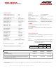
Specifications


ICT PRO SERIES POWER SUPPLY
Pro Series power supplies from ICT provide a reliable 690 Watts
of rack-mountable dc power with optional built-in battery back-
up and low voltage disconnect (LVD, option “B”) capability to
power 12, 24 or 48Vdc based systems. With an efficient wide
range power factor corrected input the units are useable world-
wide, and their built in rack mounting ears and bus-bar outputs
make installation simple.
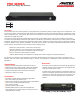
CONNECTION DIAGRAM
WARNINGS
Risk of personal injury or damage to equipment and property!
Always observe the following:
Install and operate unit in a Restricted Access location,
such as an enclosed 19” equipment rack
Operate the supply from a grounded 3-pin 120Vac or
230Vac outlet (50 or 60Hz) with a branch circuit breaker
rated 20A or less
Use an appropriate dc over-current protection device in
line with the battery connection
Use a disconnect switch or circuit breaker in series with the
battery connection, to ensure installation and service is
done with the battery disconnected
Use wire and connectors rated for the maximum load
current and size of battery fuse or circuit breaker
Ensure battery polarity is correct before connecting
Ensure load current does not exceed max rating of unit
INSTALLATION
Mount the unit in a standard 19 inch equipment rack, (ensuring
side air vents are not blocked) using rack mounting screws (not
supplied), then make the following connections using wire and
connectors appropriately rated for the maximum input and
output current rating of the unit:
Connect the supply POS output bus bar to the load positive
input
Installation (continued)
Connect the supply NEG bus bar to the load negative input
terminal
Connect a ground bonding wire from the chassis ground
stud to the rack
On units with the optional battery back-up and LVD
capability:
o Choose a lead-acid battery with a float voltage rating
that matches the Pro Series output voltage, and has
an Amp-hour (Ahr) capacity rating greater than 3
times the max current rating of the power supply (i.e.
use a 150Ahr battery or larger on a 50A supply)
o Connect the battery negative to the supply NEG bus
bar
o Connect the battery positive to an over current
protection device (fuse or breaker) and disconnect
switch
o With the battery fuse removed or disconnect switch
open connect the fuse or switch to the supply BAT(+)
terminal
o Either the POS or NEG lead may be connected to
earth ground, but the internal LVD contactor must
always be connected to the battery positive, as shown
Connect the remote on-off control or unit form-C alarm
contact monitoring wiring to the REMOTE connector if
needed, as shown in the following table:
REMOTE Connector: (use 22-26AWG wire)
Pin Number
Name
Function
1
Shutdown (+)
Remote output shutdown,
positive (2.5-16Vdc)
2
Shutdown (-)
Remote output shutdown,
return
3
NC
Alarm NC (alarm state)
4
NO
Alarm NO (alarm state)
5
Common
Alarm output common
Plug an approved AC power cord set rated for 10A or more
into the IEC type AC input connector on the back panel of
the supply (120V cord included with unit), then plug into a
grounded 3 terminal 120Vac or 230Vac outlet
DIMENSIONS (inches)
OPERATION
Switch on the unit using the front panel power switch, and
observe that it is lit. Verify the supply output voltage using a
hand held digital voltmeter. If a battery is connected install the
external fuse and close the disconnect switch.
On units with the battery back-up option connected switch off
the ac power, and verify that the battery voltage is provided to
the output load terminal using a hand held digital voltmeter.
Switch AC back on, and verify the output supply voltage rises to
the normal output rating as the battery charges.
The unit can now be left operating normally. As long as the
external back-up battery voltage is greater than the low voltage
disconnect (LVD) level the battery will be connected directly to
the supply output and will instantly power the load in case of an
AC power failure. When the battery voltage drops below the
LVD level the internal relay will open, preventing the battery
from being excessively discharged.
When AC power returns the supply will initially trickle charge
the battery until its voltage rises to the re-connect level, and it
will then close the internal LVD relay, and the battery will be
fully charged to the power supply output voltage level with
charge current limited to the maximum supply output rating.
The battery will be maintained at the supply output (float)
voltage level until AC power is removed.
Batteries connected directly to the supply output (not using the
LVD option BAT terminal) will be charged to the supply output
voltage level with a current limited to the maximum supply
output rating, with no initial trickle charge mode.
The remote shutdown input may be used to disable the supply
output by applying a voltage from 2.5 to 16V, and the form-C
alarm contacts can be used to monitor for fault conditions.
PARALLEL OPERATION
Up to 3 units without the optional battery backup capability
may be connected in parallel to power higher current loads. The
unit with the highest output voltage will initially provide most of
the load current, but as load current increases the current
supplied will tend to balance between the parallel units.
CAUTION
Risk of damage to equipment!
Ensure current supplied through the optional internal LVD
contactor cannot exceed the current rating of the unit
Do not use the internal LVD contactor for parallel
applications where load current can exceed the maximum
rating of a single unit
(Shown with battery backup/LVD, option B)