
Install Instructions


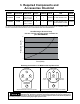


SET
+
-
Hold To
Unlock
6. Digital Control Installation, Setup & Adjustment
-6-
Temperature settings above 120° F can create a
scald hazard.
Settings
LED
Display
Setting Code Description Range
Temperature
Domestic hot water setpoint. Default is 120°F
90-150
Differential Domestic hot water temperature drop before call for heat. Default is 10°F. 5,10
Post-Purge Early boiler shutoff prior to hot water setpoint. Circulator runs until setpoint. Default is 0°F. 0,4,8*
Priority Temporarily cancels space heat to maxmize available energy for hot water. Default is 'n'. y/n
Capacity Water heater capacity; select appropriate size for proper operation. Default is 41 Gallons. 26,41,60,80,120
BTU Transfer Real-time BTU transfer estimate in 1000 BTU/Hr increments. Diagnostic readout only. 0-199MBH/Hr
*Available only when Differential setting is 10.
Error Code Description Potential Causes**
Temp Sensor Temperature sensor (thermistor) fault.
Sensor unplugged
Sensor damaged
Overheating Domestic hot water temperature has exceeded maximum setpoint.
Error in boiler plumbing
Zone valve stuck open
Leak in sensor well
Slow Heating Unit has taken over 60 minutes to reach hot water setpoint or cannot reach setpoint.
Faulty equipment
Fouled heat exchanger
No fuel
***See Troubleshooting section for additional information
Indicator Code Description
Startup Test
Idle
Heating
Displayed briefly during intial powerup to test LED display segments.
Settings are used to adjust functional operating parameters. To adjust, press and hold the SET button until the Temperature setting appears.
Cycle through settings by depressing the SET button and using the ▼ and ▲ buttons to change the settings.
Diagnostic Error Codes display a visual indicator and sound an alarm if a fault is detected. Codes clear automatically when corrected or can be reset by
interrupting power to the control for 5 seconds. To silence an alarm, depress the ▼ on the keypad.
Operating Indicators are used to display operational and functional status. Water sensor temperature may be shown for 30 seconds by pressing
the ▲ button.
Static numeric [setpoint] readout (factory default shown) indicates domestic hot water setpoint.
Alternating On and [Setpoint] is displayed during a heating cycle while the circulator pump contacts are closed.
After wiring per the appropriate diagram in this manual, insert the white
temperature sensor (thermistor) plug into the receptacle at the base of the
digital control. Zone valves can be slow actuating. Therefore, the zone valve
sensor contains a built-in temperature offset to account for the time it takes
the zone valve to fully close. This results in potable water temperature that
is representative of the digital control temperature set point. This is why it is
important to install the correct sensor into the digital control. See Page 3 for
information regarding the selection of a circulator or zone valve.
NOTE: Line-voltage and safety-circuit wiring which is external to the water
heater jacket when all panels are in place, and which is part of the appliance,
shall be protected by metal conduit, metal-clad cable or raceways. “Power
Limited Circuit Cable” needed not be provided with the protection specified
above if it is securely fastened to the appliance jacket and follows the contour
of the appliance jacket. Thermoelectric wiring shall be exempt from this
provision.
NOTE: Strain relief shall be provided for all conductors leaving an enclosure.
For low-voltage wiring, strain relief at the point of exit from an enclosure is
not necessary if, by wire location or support, protection is provided against
accidental strain.
Front Panel
Control
Screws (4)
Wiring Cover
Ground Screw
Temperature
Sensor Plug
Conduit Holes (3)