instruction manual 10.
AMX Limited Warranty and Disclaimer AMX Corporation warrants its products to be free of defects in material and workmanship under normal use for three (3) years from the date of purchase from AMX Corporation, with the following exceptions: • Electroluminescent and LCD Control Panels are warranted for three (3) years, except for the display and touch overlay components that are warranted for a period of one (1) year.
Table of Contents Table of Contents Product Information .................................................................................................1 Specifications .................................................................................................................... 1 Cleaning the Touch Overlay.............................................................................................. 2 Installation .....................................................................................
Table of Contents Programming .......................................................................................................... 25 Serial Commands............................................................................................................ 25 System Send_Commands .............................................................................................. 28 Video Send_Commands .................................................................................................
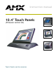
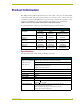
Product Information Product Information The AMX™ CA10, CV10 and CG10 touch panels contain a 10.4", 256-color active matrix liquid crystal display (LCD). The self-contained enclosures use a microprocessor to control a wide range of multimedia equipment. The TPDesign3 touch panel design program makes it possible to create custom pages with buttons, icons, sliders, bargraphs, time displays, logos, and drawings. All Decor-style references in this manual relate to wall mounted panels.
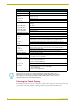
Product Information Specifications (Cont.) Power 12 VDC @ 1 A Memory Standard: 5 MB (4 MB flash) Weight: Decor • 6.0 lbs. (2.7 kg) Rack-mount • 6.0 lbs. (2.7 kg) TiltScreen VGA Input Resolutions: • 4.6 lbs. (2.1 kg) (The frame frequency [FF] calculations are based on monitor type and VGA settings.
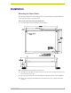
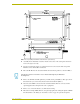
Installation Installation Mounting the Touch Panel The following paragraphs describe mounting the Decor and rack-mount touch panels. TiltScreen touch panels can be placed on any flat surface. Decor style panels with low-profile Backboxes 1. Cut out the surface using the dimensions shown in FIG. 1. FIG. 1 AXD-CA10 and low profile Backbox cutout dimensions 2. Carefully insert a flat-blade screwdriver into the release slot on the touch panel’s faceplate and remove the engraved overlay. 3.
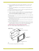
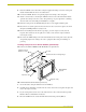
Installation 5. Disconnect the AXlink connector from the Central Controller, RS-232 connector, and the optional graphic/video wiring from the external RS-232 device connected to the source equipment. 6. Thread the incoming AXlink, RS-232, and optional graphic/video wiring through the lowprofile Backbox. 7. Fasten the low-profile Backbox using the #6-32 machine screws supplied with the enclosure. 8. Attach the data and power wiring to the touch panel. 9.
Installation FIG. 3 Decor style (AXD) and CB-TP3 cutout dimensions (solid surfaces) 2. Carefully insert a flat-blade screwdriver into the release slot on the touch panel’s bezel and remove the engraved overlay. 3. Lay the touch panel facedown on a soft cloth and remove the screws from the low-profile Backbox; remove the Backbox and discard. 4. Place the CB-TP3 into the cutout and mark the threaded insert positions, as shown in FIG. 3.
Installation 9. Fasten the CB-TP3 to the solid surface using the supplied mounting screws. The touch panel must be installed with the release slot at the bottom. 10. Connect the AXlink, RS-232, and optional graphic/video wiring to the touch panel. 11. Test the connection by reconnecting the AXlink connector to the Central Controller and the optional video wiring to the video source. The panel beeps on power-up. Before continuing, disconnect all connections until panel installation is complete. 12.
Installation FIG. 5 Decor style (AXD) and CB-TP3 cutout dimensions for plasterboard 5. Remove the CB-TP3 and drill four #6-32 insert holes. Then, place a threaded insert (or screw anchor) into each hole. 6. Disconnect the AXlink connector from the Central Controller, RS-232 connector, and the optional graphic/video wiring from the source equipment. 7. Remove one or more knockouts to accommodate the wiring as required. 8.
Installation 14. Remove the backing from the adhesive tape strips; press the engraved overlay onto the faceplate. Once attached to the faceplate, the security screws cannot be replaced without removing the overlay. 15. Reconnect the AXlink wiring to the Central Controller, RS-232 wiring to the mouse (if used), and optional graphic/video wiring to the source equipment. The touch panel beeps on powerup. Installing rack-mount panels (AXM-CA10/PB) 1.
Installation The maximum wiring lengths for using AXlink power are based on a minimum of 13.5 VDC available at the Central Controller's power supply. Refer to the Specifications section on page 1 for more information on power requirements. Wiring Guidelines Maximum Wiring Length Wire Size Color Active Color Graphic Color Video 18 AWG 143.14 feet (43.63 m) 93.90 feet (28.62 m) 130.05 feet (39.64 m) 20 AWG 90.56 feet (27.60 m) 59.41 feet (18.11 m) 78.17 feet (23.83 m) 22 AWG 56.46 feet (17.
Installation GND - AXP/TX AXM/RX PWR + AXM/RX To the external Central Controller PWR + GND AXP/TX To the touch panel AXlinx/PWR connector Top view Top view FIG. 7 AXlink wiring diagram If you are using power from AXlink, disconnect the wiring from the Central Controller before wiring the touch panel.
Installation Never connect both power wires from the power supply and Central Controller to the PWR terminal on the touch panel AXlink connector. Only the power supply’s PWR wire should be connected to the touch panel AXlink connector. If both sources are used to provide power to the touch panel, an electrical hazard is created and the threat of both equipment damage and injury is likely. 4. Place the PWR wire from the power supply into the open clamp position for PWR on the touch panel AXlink connector.
Installation Using the VGA IN HD-15 (male) high-density connector Connect the VGA source equipment’s HD-15 (female) connector to the VGA IN HD-15 (male) high-density connector on the rear panel of the touch panel. The table below lists the VGA IN HD-15 connector pinouts.
Installation 10.
Installation 14 10.
Designing Touch Panel Pages Designing Touch Panel Pages There are two ways to approach creating touch panel pages: ! TPDesign3 - Refer to the TPDesign3 Touch Panel Program (Version 3. 16 or higher) Instruction Manual for more information. ! On-board editor This section describes the basics of using the on-board editor to create pages and buttons. For more information, refer to the G3 Firmware Design and Reference instruction manual.
Designing Touch Panel Pages General Button Categories (Cont.) Status buttons Status buttons always have a dark fill with light letters and have no functionality except to display information. Operation bars Operation bars appear in the place of the Editor bar, after selecting a button or page edit operation. The operation bar indicates which edit function is currently active. When an edit operation is selected, it remains active until you press EXIT.
Designing Touch Panel Pages FIG. 11 Setup page 4. Press EDITOR to enable Edit mode. The EDITOR button is highlighted in the Protected Setup page when enabled, as shown in FIG. 12. FIG. 12 Protected Setup page with the active EDITOR button 5. Press EXIT to close the Protected Setup page and return to the Setup page (now in Edit mode). 6. Press EXIT again to return to the Main page. The EDIT button appears at the top of the page indicating Edit mode is active. 7. Press EDIT to open the Edit bar.
Designing Touch Panel Pages Setting the Device Base Press the DEVICE BASE option, in the Protected Setup page (FIG. 12), to assign a base (starting) device address to the touch panel. 1. Enter the base address for the touch panel. The base address range is from 1 - 255. Standard device addresses begin at 128. 2. Press ENTER to save the value. Setting the Device Used Use the DEVICE USED option in the Protected Setup page (FIG.
Designing Touch Panel Pages A Video signal can only be displayed within a Video WIndow Button. From the Edit bar, go to Button > Add. Touch the screen to size the button. Open Button > Properties and select Video Window from the Button Type section. Refer to the G3 Firmware instruction manual for more detailed information. Resizing a button 1. Press BUTTON on the Edit bar to open the BUTTON menu. 2. Press RESIZE. Then, touch any edge of the button and drag.
Designing Touch Panel Pages If DEVICE USED is set to 4 and Base Device Number is 128, the Controller recognizes bus devices 128 - 131. The panel will not allow you to enter a device number greater than the DEVICE USED without first displaying a decision box asking if you accept the new selection or not. 3. Press ENTER to save the device number, close the keypad, and return to the Button Properties page. 4. Press CHAN to open the keypad and enter a channel value of 1 - 255.
Designing Touch Panel Pages Setting the button colors for channel-off conditions 1. Press any button to open the Button Properties page. 2. Press BORDER under CHANNEL OFF in the Button Properties page. The color palette appears. Select a color to set as the border. 3. Press the FILL button in the Button Properties page to open the palette. Select a color to set as the fill. 4. Press the TEXT button to open the palette. Select a color to use for the text. 5.
Designing Touch Panel Pages 6. In the What To Send area, select one or more of the available options (All Bitmaps, All Icons, All Fonts). 7. Select the mode of communication with the touch panel (RS-232 and AXlink). Confirm that the correct panel is selected by verifying the ID values with the Base Address assigned to the touch panel in the Protected Setup page. 8. After clicking Connect, the Available Panels list appears in the Available Panels field.
Designing Touch Panel Pages 4. Press NUM to open a keypad and set the level number assigned to the device. 5. Enter a number 1 – 8. Each device can have from 1 – 8 levels except joysticks, where the range is 1 – 7. 6. Press ENTER to save, close the keypad, and return to the Button Properties page. 10.
Designing Touch Panel Pages 24 10.
Programming Programming You can program the touch panel to perform a wide variety of operations using AXCESS Send_Commands and variable text commands. Use the commands described in this section to program the touch panel. Refer to the AXCESS Programming Language instruction manual for complete information. Serial Commands Serial Commands are used in the AxcessX Terminal Emulator Mode. These commands are case insensitive. Serial Commands ?PAR Returns panel parameters to the PC terminal.
Programming Serial Commands (Cont.) ECHO ON Syntax: Turns On character echo. Example: "ECHO ON" ECHO ON The character echo is sent back to the computer. ECHO OFF Turns Off character echo. Syntax: "ECHO OFF" Example: ECHO OFF The character echo is not sent back to the computer. GET CAL Gets the calibration variables. Syntax: "GET CAL" Example: GET CAL Gets the calibration variables on the touch panel. HELLO Verifies that serial communication is working properly.
Programming Serial Commands (Cont.) SET CAL Sets the calibration variables. Syntax: “SET CAL " Example: SET CAL 2F 3A 2B 62 Sets the calibration values on the touch panel. SETUP Syntax: Puts the touch panel on the Setup Page. Example: "SETUP" SETUP Flips the touch panel to the Setup page. VER Syntax: Restores the current version. Example: "VER" VER Returns the current version of the main firmware.
Programming System Send_Commands System Send_Commands are stored in the Controller and direct the touch panel to perform various operations. System Send_Commands $SP Translates the ¦ and translates it as a carriage return to the next line. Sends data out Syntax: the serial port with "’$SP ""’" trailing CR and LF. Example: SEND_COMMAND TP,"’$SP "CALIBRATE"’" Sends the Calibrate command to another panel through the Serial Port.
Programming System Send_Commands (Cont.) BAUD The baud rate can also be set in the Protected Setup page’s BAUD level indicator. Sets the program port baud rate. Syntax: "’BAUD ’" Variable: baud rate = 38400, 19200, 9600, 4800, 2400, 1200, 600, and 300 Example: SEND_COMMAND TP,"’BAUD 38400’" Sets the Baud rate to 38400. BEEP This beep command sounds one tone for a time length of 50 milliseconds. Gives an output of Syntax: one beep.
Programming System Send_Commands (Cont.) DBEEP Gives a double beep output. This command only works if the Double Beep value in the Protected Setup page is set to On. Syntax: "’DBEEP’" Example: SEND_COMMAND TP,"’DBEEP’" Double beeps the panel. ILEV Inverts the joystick axis.
Programming System Send_Commands (Cont.) PPOF Syntax: Closes a specific popup page. Variable: "’PPOF-’" page name = 1 - 50 ASCII characters Example: SEND_COMMAND TP,"’PPOF-Popup Page 1’" Closes Popup Page 1. PPON Opens a specific popup page. Syntax: "’PPON-’" Variable: page name = 1 - 50 ASCII characters Example: SEND_COMMAND TP,"’PPON-Popup Page 1’" Opens Popup Page 1. QBEEP Stops all beeps.
Programming System Send_Commands (Cont.) TPAGEON Syntax: Activates page tracking.
Programming System Send_Commands (Cont.) TPAGEOFF Syntax: Deactivates page tracking. Example: "’TPAGEOFF’" SEND_COMMAND TP,"’TPAGEOFF’" Deactivates the page tracking option. WAKE Syntax: Deactivates screen-saver mode and resets the sleep timer. Example: "’WAKE’" SEND_COMMAND TP,"’WAKE’" Deactivates the touch panel screen-saver mode and resets the sleep timer. XMRT Sets the new network communication retry value for the panel and SoftROM.
Programming Video Send_Commands (Cont.) @VBW Syntax: Sets the video to black/white or color. Variables: "’@VBW ’" Black/White input setting = 0: Color 1: Black and White Example: SEND_COMMAND TP,"’@VBW 1’" Sets the video output to black and white. @VCT Sets the video contrast. Syntax: "’@VCT ’" Variables: ASCII contrast setting = 0 (min) - 255 (max) Example: SEND_COMMAND TP,"’@VCT 128’" Sets the video contrast to 128.
Programming Video Send_Commands (Cont.) @VSD Resets the following video attributes to their default settings: Resets video default settings. Syntax: Brightness, Contrast, Saturation, Hue, Interlace "’@VSD’" Example: SEND_COMMAND TP,"’@VSD’" Resets the video defaults. @VST Sets the video saturation. Syntax: "’@VST ’" Variables: ASCII saturation setting = 0 (min) - 255 (max) Example: SEND_COMMAND TP,"’@VST 128’" Sets video saturation to 128.
Programming VGA Send_Commands (Cont.) VGGC Syntax: Sets the green VGA signal intensity (brightness). Variable: "’VGGC-’" ASCII green intensity setting = 0 - 67 Example: SEND_COMMAND TP,"’VGGC-0’" Sets the green VGA signal intensity to 0 (minimum). VGHP Syntax: Moves the VGA display horizontally to the right or left.
Programming VGA Send_Commands (Cont.) VGVP Syntax: Moves the VGA display vertically up or down. Variable: "’VGVP-’" ASCII vertical position setting = 0 - 15 Examples: SEND_COMMAND TP,"’VGVP-10’" Centers the VGA display vertically. Programming Numbers The following information provides the programming numbers for colors, fonts, and borders Colors can be used to set the colors on buttons, sliders, gauges, and pages.
Programming Border styles can be used to program borders on buttons, sliders, and gauges. Border Styles and Programming Numbers No. Border styles No.
Programming Shorthand Send_Commands (Cont.) @CFF This only works if the specified background color is not the same as the current color. Sets the OFF feedback fill color to the specified color. Syntax: "’@CFF’,," Variables: variable text address = 1 - 255 color number = See the Colors and Programming Numbers table on page 37. Example: SEND_COMMAND TP,"’@CFF’,1,72" Sets the OFF feedback fill color to White for variable text button 1.
Programming Shorthand Send_Commands (Cont.) @CTN This only works if the specified background color is not the same as the current color. Sets the ON feed- Syntax: back text color to "’@CTN’,," the specified Variables: color. variable text address = 1 – 255 color number = See the Colors and Programming Numbers table on page 37. Example: SEND_COMMAND TP,"’@CTN’,1,72" Sets the ON feedback text color to White for variable text button 1.
Programming Shorthand Send_Commands (Cont.) @PPF Deactivates a popup page on a touch panel page. If a page name is empty, the current page is used. If a pop-up page is part of a group, the whole group is deactivated.
Programming Shorthand Send_Commands (Cont.) @PWD Syntax: Sets the password "’@PWD-’" for the Page Flip Variable: on the touch page flip password = 0 - 9999 panel. Example: SEND_COMMAND TP,"’@PWD-1988’" Sets the page flip password to 1988. @RDW Redraws the current screen. Syntax: "’@RDW’" Example: SEND_COMMAND TP,"’@RDW’" Sends a message to the touch panel to redraw the screen. @SSL Changes the Sleep string sent to the Controller when the touch panel activates sleep mode.
Programming Color Send_Commands Use the color Send_Commands to set the colors for text, buttons, and pages. Use the same command for setting gray scale values only change the color number value to reflect the gray scale (72-86) value. Color Send_Commands CALL You must use the variable text assignments to change button colors (see the Colors and Sets the colors for Programming Numbers table on page 37). a variable text but- Syntax: ton.
Programming Color Send_Commands (Cont.) CFOFF Syntax: Sets the OFF feedback fill color to the specified color. Variables: "’CFOFF-’" variable text address = 1 - 255 color number = See the Colors and Programming Numbers table on page 37. Example: SEND_COMMAND TP,"’CFOFF1-72’" Sets the OFF feedback fill color to White for variable text button 1.
Programming Variable Text Send_Commands Use variable text Send_Commands to set the borders, fonts, and text. Variable Text Send_Commands !B Sets a specific button to On or Off. Syntax: "’!B’,," Variables: variable text address = 1 - 255 ON = 0 OFF = 1 Example: SEND_COMMAND TP,"’!B’,128,1" Sets button 128 Off. BTOF Sets a specific button's active state to Off.
Programming Variable Text Send_Commands (Cont.) FONT Syntax: Changes the font size (or style) of the text in a specific button. Variables: "’FONT-’" variable text address = 1 - 255 font size = See the Font Styles and Programming Numbers table on page 37. Example: SEND_COMMAND TP,"’FONT1-6’" Changes variable text button one font to hollow medium. !I Shorthand version of 'ICON' command.
Programming Shorthand Variable Text Commands The table below lists the shorthand variable text commands you can use with the touch panel. The shorthand command data is one-byte, non-ASCII format except for pages, passwords, text, and bitmap names. Shorthand Variable Text Commands @BMF This command allows you to program up to 12 attributes on one command line. Syntax: Sets multiple attributes to a but"’@BMF’,,’’" ton, slider, or Variables: gauge.
Programming Shorthand Variable Text Commands (Cont.) @BOR Syntax: Sets the border style on a button. Variables: "’@BOR’,," variable text address = 1 - 255 border style = See the Border Styles and Programming Numbers table on page 38. Example: SEND_COMMAND TP,"’@BOR’,65,11" Sets the border style to Double shadow on button 65. @ENA Syntax: Enables/disables buttons based on the variable text channel.
Programming Shorthand Variable Text Commands (Cont.) @JUS Syntax: Sets the text alignment on a button. Variables: "’@JUS’,," variable text address = 1 - 255 text alignment = 1 - 9 as shown in the following alignment chart 1 2 3 4 5 6 7 8 9 Example: SEND_COMMAND TP,"’@JUS’,9,5" Centers the text on button 9. @SHO Sets a specific button to on or off.
Programming Button String Commands The table below lists string commands you can assign to buttons by using the touch panel editor. Select the PROPERTIES option in the Edit bar, press the target button, and enter the string command with the Touch Panel keyboard. The string command is sent to the control system when you press the button. Button String Commands $CU Turns the cursor display On and Off.
Programming Button String Commands (Cont.) $SP Syntax: Sends data out "$SP""" through the serial Variables: port of the source panel to a destina- data = Serial string command tion panel. Examples: $SP "CALIBRATE" Sends the Calibrate command to another panel through the Serial Port. $SP "$SC 1,"’@TXT’,1,’TEST’"" Uses the $SP command to send a Send Command ($SC ***) to another panel through the Serial Port. This is an on-panel button string that is entered using on-screen keyboard.
Programming 52 10.
Upgrading the Firmware Upgrading the Firmware Your PC must be connected to the PROGRAM DB9 connector on the Controller or camera control unit connector using a Programming Cable in order to upgrade the firmware. If power is lost during the download process, the unit powers up with the same set of code it had prior to the download. There is a small window during which a loss of power can be catastrophic.
Upgrading the Firmware 5. Click OK twice to exit from the Master Communication Settings dialog box and to establish the communication. 6. Select Edit > Preferences, from the General - Communications section 7. Select the Enable Online Tree option to view the Connected devices from within the Project Navigator window. The next step is to set the System value. If the connection fails to establish, try selecting a different COM port. 8.
Upgrading the Firmware Selected Firmware file Device number listing of detected Axcess devices Device, Port and system number of panel. Query Online Devices allows the user to refresh the list of detected Axcess devices FIG. 17 Select New 10.4 Firmware File for download page 17. Click Download to open the Confirm Communication Settings dialog, where you can review and confirm your Comm Settings and Target Device information before the download begins.
Upgrading the Firmware 2. Select Tools > Master Communication Settings from the Main menu. 3. Press the NetLinx radio button from within the Platform section of the Communication Settings dialog box (FIG. 18). Enter an IP Address FIG. 18 Communication Setting tab 4. From the Communications Port drop-down list, choose Network. This indicates the IP Address on the master is being reached from within a network connection. 5. Enter the IP Address information displayed on the Networking tab.
Upgrading the Firmware 11. Select Tools > Firmware > Download to Axcess Device, from the Main menu, to open the Communication Settings dialog box. 12. Click Browse to navigate to the directory containing the firmware files. Once a directory containing one or more TSK files is specified, a list of available TSK files is displayed in the upper table in this dialog. 13. Select the desired Download TSK file from the list of available files. 14.
Upgrading the Firmware Configuration To configure the communication setting for the SoftROM program: 1. Press F1 to open the Configuration screen. 2. Using the up/down arrow keys, select the communications port you are using to interface with the controller and press ENTER. 3. Using the right arrow key, move to the BAUD RATE column. Then, use the up/down arrow keys to select the interface communications speed and press ENTER. Be sure the BAUD RATE selections match the setting on the Controller. 4.
Changing the LCD Viewing Angle Changing the LCD Viewing Angle You can reset the viewing angle on the Decor-style wall mount and Rack-mount touch panels to accommodate the various installation locations and viewing angles. The two most frequent locations are on a wall or podium. In the first location (wall), a user is looking at the screen from a 12 o’clock position (looking down on it). This view typically requires the user to view images on the LCD at an angle above the true center of the screen.
Changing the LCD Viewing Angle Jumper 6 3 2 1 FIG. 20 Open circuit card and JP6 jumper location Bezel mounting screws Rotate bezel 180 degrees Bezel/faceplate Release slot FIG. 21 Bezel mounting screws and release slot locations 17. Place the engraved overlay back onto the touch panels’ bezel/faceplate. 60 10.
Replacing the Batteries Replacing the Batteries There are two lithium batteries on the touch panel card, with a life of approximately 2.5 years. They protect stored commands and pages against a power outage. The batteries are not used when DC power is supplied to the touch panel. Write down the replacement date on a label by adding 2.5 years to the date of installation, and attach it to the panel for future reference. FIG. 22 Lithium battery and socket Static electricity can damage electronic circuitry.
036-004-1783 6/03 ©2003 AMX Corporation. All rights reserved. AMX, the AMX logo, the building icon, the home icon, and the light bulb icon are all trademarks of AMX Corporation. AMX reserves the right to alter specifications without notice at any time. *In Canada doing business as Panja Inc. AMX reserves the right to alter specifications without notice at any time.