
Instruction manual

Product Overview and Specifications
20
Instruction Manual – DXLink™ Twisted Pair Transmitters/Receiver
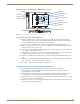
ICS LAN10/100 Connector
The ICS LAN 10/100 (RJ-45) connector provides for Ethernet 10/100 connectivity (e.g., receiving
SEND_COMMANDs and downloading firmware update files). For pinout and LED information, see page 50.
RS-232 (Serial) Port
The RS-232 port (serial data interface) is a 3-position screw terminal block which accepts data from the source
device and transfers it via the twisted pair cable to the HDMI RX, which in turn transfers the data to the
destination device. The transfer of data can also be made from the destination to the source. In addition to being
directly connected to a device, this port can be connected as an independent native NetLinx control port from a
networked NetLinx Central Controller.
IR RX Port
The IR RX port is used for IR control (see page 27). This port is a 3.5 mm stereo jack. In addition to being directly
connected to a device, this port can be connected as an independent native NetLinx control port from a networked
NetLinx Central Controller.
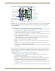
IR TX Port
The IR TX port is used for IR control (see page 27). This port is a 2-way mini-Phoenix connector. In addition to
being directly connected to a device, this port can be connected as an independent native NetLinx control port
from a networked NetLinx Central Controller.
USB Port
The USB-B port on the rear of the Multi-Format TX and HDMI TX is connected to a PC and supports a USB
device. This is the Host port that is used in conjunction with the USB-A port on the rear of the HDMI RX for
sending keyboard / mouse commands to a connected PC at the Transmitter. (For USB port information, see
page 26.)
DXLink Output Connector
The DXLink (RJ-45) connectors transport digital video, embedded audio, Ethernet, and bidirectional control over
twisted pair cable to DXLink devices or boards (or an HDMI RX), including digitally transcoded analog video
signals. The DXLink path supports HDCP. The DXLink line also supports power from an Enova DGX Switcher
and from some Enova DVX Solutions to power the module. For pinout and LED information, see page 50.
Ground Screw
The ground screw is used for creating a technical ground for the ungrounded sources/destinations with respect to
the DXLink Transmitters/Receivers and switcher (see page 47).
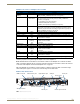
Power Jack
Important: If desktop power is used to power the Transmitter, only the provided desktop power supply should
be used and it must not
be altered in any way. Remote power can also be provided via a switcher, PDXL-2
(FG1090-170), or PS-POE-AT-TC (FG423-84).
The power receptacle is a 2.1 mm DC jack for connecting power. Power can come from a locally connected DC
supply of 12 V. The automatically adjusting universal 110/220 IEC power supply is provided. The power supply is
ENERGY STAR
®
qualified to ensure maximum efficiency and savings.
Note: Transmitter Modules can also be powered via the DXLink connector when attached to a DXLink Input
Board in an Enova DGX Switcher. We recommend calculating the power budget for the switcher to maintain
the redundancy of its power supplies (see page 41).