
Instruction manual


Installation and Setup
44
Instruction Manual – DXLink™ Twisted Pair Transmitters/Receiver
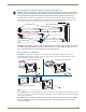
Setting DIP Switch #1 to Enable/Disable Access to ICS LAN 10/100 Port
The #1 Toggle is used for enabling/disabling network activity over the physical ICS LAN 10/100 port, which allows
Ethernet pass through. It does not affect network activity over DXLink. (For SEND_COMMANDs to disable/enable
ICS LAN functionality, see page 96.)
Note: #1 Toggle settings do not apply to Wallplate TX & Decor Wallplate TX – leave #1 Toggle OFF.
Tip: Common setup scenarios and their DIP switch settings are provided in a table on page 45.
#1 Toggle Settings
OFF (default) – When the #1 Toggle is set to OFF, network activity over the ICS LAN 10/100 port is
disabled.
ON – When the #1 Toggle is set to ON, network activity over the ICS LAN 10/100 port is enabled.
Installation Options
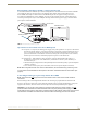
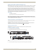
Option A – For a network connection between a Transmitter and a Receiver where only one of them is
connected to a LAN, set the #1 Toggle to ON for the unit that is connected to the network.
Caution: Option A – Do not connect both
the Transmitter and the Receiver to a common LAN as a network
loop will result. For information on avoiding network loops, see page 43.
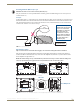
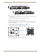
Option B – When a Transmitter or Receiver is connected to a DXLink input or output on an Enova DGX
Digital Media Switcher or Enova DVX switcher, the switcher provides a network connection allowing the
Transmitter or Receiver to appear in the online tree in NetLinx Studio (#3 Toggle must be set to ON). For
connecting the Transmitter or Receiver to other equipment using the ICS LAN 10/100 port, the #1 Toggle
must be set to ON.
Caution: Option B – Because the DXLink connection carries network activity passed from the switcher,
do not connect
the ICS LAN 10/100 port on the Transmitter or Receiver to the same LAN as the switcher
because a network loop will result. For information on avoiding network loops, see page 43.
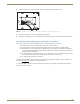
Setting DIP Switch #2 to Set the DXLink Mode
#2 Toggle can be set to automatically or manually select the DXLink Mode (to either Extender or Endpoint) for a given
Transmitter/Receiver Module. Default state for #2 Toggle OFF is auto selection of DXLink Mode based on connection
to another device. When it’s ON, the default is Endpoint Mode (used for Master controlled serial/IR data transfer).
Note: #2 Toggle settings do not apply to Wallplate TX & Decor Wallplate TX – leave #2 Toggle OFF.
Tip: Common setup scenarios and their DIP switch settings are provided in a table on page 45.
#2 Toggle Settings
OFF (default) – When #2 Toggle is set to OFF, the Transmitter and Receiver will each auto-discover* what
type of DXLink equipment they are connected to and will automatically self-configure to be in one of two
DXLink Modes based on the connection:
Extender Mode – This mode is automatically selected when a TX and RX are connected directly to each
other (a standalone pair). The Transmitter and Receiver act like a simple extender, and serial and IR data is
passed through them.
Endpoint Mode – This mode is automatically selected when a module is connected directly to a DXLink
port on a switcher. Serial and IR operations are handled by the host providing control of endpoints. The
Master’s programming specifies where IR and serial commands are sent (this is handled independently
from the routing of the video signals).
* Any time the DXLink connection is re-established or power is cycled on a module, the auto-discovery process will
take place, as long as the #2 Toggle remains in the OFF position.
ON – When #2 Toggle is set to ON, the auto-discover feature is disabled and the module can be manually set
to either Endpoint Mode (default) or Extender Mode. In Endpoint Mode, when the module is connected to a
switcher or a separate NetLinx Master**, IR and serial operation are only handled via the host.
** When standalone modules require IR and/or Serial control by a separate NetLinx Master, then they need to be in
Endpoint Mode. Only one must be connected via the ICS LAN 10/100 port to the Master or to a LAN with the Master on
it. This requires #1 Toggle to be ON to enable the ICS LAN port. #2 Toggle needs to be ON to place the modules in
Endpoint Mode (if needed), and #3 Toggle needs to be ON to enable network connectivity.