instruction manual ALD-H48 Network Lighting Solution Lighting Control
AMX Limited Warranty and Disclaimer AMX Corporation warrants its products to be free of defects in material and workmanship under normal use for three (3) years from the date of purchase from AMX Corporation, with the following exceptions: • Electroluminescent and LCD Control Panels are warranted for three (3) years, except for the display and touch overlay components that are warranted for a period of one (1) year.
Software License and Warranty Agreement LICENSE GRANT. AMX grants to Licensee the non-exclusive right to use the AMX Software in the manner described in this License. The AMX Software is licensed, not sold. The AMX Software consists of generally available programming and development software, product documentation, sample applications, tools and utilities, and miscellaneous technical information. Please refer to the README.
Table of Contents Table of Contents Overview ....................................................................................................................1 Getting Started ..........................................................................................................3 Step 1: Downloading The ALD-H48 Workspace .............................................................. 3 Step 2: Setting The ALD-H48 IP Address ........................................................................
Table of Contents Via 232 ............................................................................................................................ 37 Via Ethernet: ...................................................................................................................
Overview Overview The ALD-H48 from AMX is a Lutron lighting solution with a complementary Duet module. The result is a Lutron device that functions within a NetLinx project. After you have installed the ALD-H48, using the installation documentation included with the unit, you can create a NetLinx project and configure the dimmers. You need NetLinx Studio v2.3 or higher and a NetLinx Master capable of running Duet modules (firmware version 3.0.XXX or higher).
Overview 2 ALD-H48 Lighting Controller
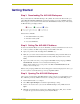
Getting Started Getting Started Step 1: Downloading The ALD-H48 Workspace First you must attain the ALD-H48 Workspace file (.AXW). To download the Duet module go to either amx.com > Dealers > InConcert or the Product Catalog page for the ALD-H48. From the InConcert page you can search for and download the ALD-H48 Duet module, they are indicated by the D within the legend displayed below. FIG. 1 Module Legend Included in the .AXW file: The NetLinx Main Code (.AXS) The Duet module (.
Getting Started You can also make any additional edits to the ALD-H48 project or elect to send the file to the NetLinx Master as is. There is a "simple" version of the ALD-H48 files. These files are intended for demonstration purposes only. Step 4: Transferring The ALD-H48 Project to A NetLinx Master NetLinx Studio can transfer the ALD-H48 project file to any connected NetLinx Master with firmware version 3.XX or higher. 1. Select Tools > File Transfer to open the File Transfer dialog. 2.
Using The Web Interface Using The Web Interface Addressing The Dimmers via The Web Interface Once you have installed the ALD-H48 and dimmers using the hardware installation literature included with the unit, you must now address the dimmers. You can only select addresses available on the bus to which the dimmer is physically connected. For example, if you want to assign address 17 to a particular dimmer, it must be connected to bus 3 of the ALD-H48 as indicated below.
Using The Web Interface FIG.
Using The Web Interface Controlling Dimmers via The Web Page Once a dimmer has been addressed, you have access to a few basic level controls from the master’s web page. 1. Click the button Dimmer Control to open the Dimmer Control page. (FIG. 4) FIG. 4 Dimmer Control Listed in the column on the left are all dimmer addresses available for control. On the right is a percentage bargraph representation of the current state of the selected dimmer. 2.
Using The Web Interface Establishing And Modifying Scenes Once your dimmers have been addressed and states set, you can create a scene. A scene is a collection of dimmers with specific states for each dimmer, i.e., Scene 1 could be set as a meeting scene where Dimmers 1 and 12 ramp down to 45%, Dimmers 6 and 14 ramp to 80% and Dimmers 2 through 5 ramp to 0% and all dimmers delay 10 seconds after the scene is selected before initiating. A dimmer can be a part of many different scenes. To create a scene: 1.
Using The Web Interface FIG. 6 Modify Scene 3. Moving left to right the first field is a check box. Placing a check in the box includes the dimmer in the scene. Once you have all of your desired dimmers selected you can set the Delay time. The delay time is the duration, in 1/10ths of seconds, it takes the dimmers to respond to the button push. 4. Type a number value in the field Delay Time. The next field is the ramp time.
Using The Web Interface Establishing And Modifying Groups For the purpose of controlling several dimmers at one time you can place them into groups. The groups can then be manipulated collectively. 1. Click the Groups button to list all available group numbers. 2. Click the Modify button for the Group you would like to set. This opens the Modify Group page. Shown below. FIG. 7 Modify Group In the column on the left is a list of all dimmers available for adding to the group.
Using The Touch Panel Pages Using The Touch Panel Pages Touch Panel Main Page After you have loaded the Lutron_H48.TP4 sample file, it is displayed on the Main Page (FIG. 8) of your touch panel. The Main Page is displayed after each subsequent reboot. FIG. 8 Touch Panel Main Page Near the bottom of the panel page are the 4 buttons for configuring your system. Click on any of the buttons to access their pages. The buttons are: Setup - access addressing mode and set addresses for connected dimmers.
Using The Touch Panel Pages Dimmer Light Adjustment The dimmer light adjustment allows you to turn on and off specific dimmers, ramp dimmers up and down and set dimmers to specific levels between 0 and 100%. Toggle Dimmer Ramp Up/Down Keypad Dimmer On Open Keypad Dimmer Off FIG. 9 Dimmer Light Adjustment Toggle Dimmer - moves through all addressed dimmers connected to the ALD-H48. Dimmer Off - turns the selected dimmer off. Dimmer On - turns the selected dimmer on.
Using The Touch Panel Pages Push the Ramp Up and Ramp Down buttons to raise and lower the dimmer levels incrementally. 2. Push the "%" button to open the keypad, type the percentage value for the dimmer. 3. Push Go to set the dimmer intensity. Setup Page Opening the Setup page places the ALD-H48 in addressing mode which will allow you to allocate addresses to attached dimmers. It is recommended you address your dimmers at the time your lighting system is first installed.
Using The Touch Panel Pages Addressing Dimmers 1. From the Main page, push the Setup button. 2. Push the Addressing Off button, this will place the ALD-H48 in addressing mode. 3. Push the dimmer you wish to address three times. The serial number of the dimmer appears at the bottom of the page as a confirmation. 4. Select the address number for the dimmer. Remember to select the bus to which the dimmer is physically attached.
Using The Touch Panel Pages FIG. 11 Groups Page The sample touch panel only includes support for 2 groups but the system supports 48 groups. There is a limited amount of editing functionality available on the test pages. While it is not possible to delete a group from this page once the group has been established, you can overwrite an existing group. To Group 1 - Open control of dimmers associated with Group 1. To Group 2 - Open control of dimmers associated with Group 2.
Using The Touch Panel Pages Scenes Page Accessing the Scenes page allows you to create and edit lighting scenes. A lighting scene is a collection of dimmers changing to specific intensity percentages (0-100%), fading in or out (up to 1 minute) and having a delay time (up to 2 hours). All of the Scene parameters come together for specific lighting needs, i.e., a slideshow presentation.
Using The Touch Panel Pages Delete Scene Buttons - Push the button to remove all dimmers and settings for the dimmers. This removes everything contained within the scene. Back Button - Return to the Main page. Creating A Lighting Scene 1. From the Main page, push the Scenes button. 2. Select the scene you want to configure, push the To Scene... button. 3. Push the Bus Toggle buttons until you find the bus that hold the dimmer you want included in the scene. 4.
Using The Touch Panel Pages 18 ALD-H48 Lighting Controller
Advanced Programming Advanced Programming Introduction This is a reference manual to describe the interface provided between an AMX NetLinx system and a Lutron H48 Lighting Controller. The H48 supports an IP protocol. Further, the H48 supports 48 light loads (dimmers) and 24 keypads (addressable as keypad 1 through 24). Overview The COMM module translates between the standard interface described below and the H48 protocol.
Advanced Programming Implementation To interface to the AMX Lutron_H48_Comm.jar module, you must: 1. Define the device ID for the H48 to be controlled. 2. Define the virtual device ID that the Lutron_H48_Comm.jar Duet module will use to communicate with the main program and User Interface. NetLinx virtual devices start with device number 41001. 3. If a touch panel interface is needed, a touch panel file Lutron_H48.TP4 and module Lutron_H48_UI.axs have been created for testing. 4.
Advanced Programming Port Mapping This module uses multiple virtual devices in order distinguish events for one keypad from another. Port Mapping Virtual Device Channels Levels Control Feedback 41001:n:0 - {keypad n=1..24} 1..24 & 101..124 none PUSH RELEASE ON OFF FLASH Channel Assignment and Feedback While channel 251 is ON, the AMX system and the H48 are communicating. While channel 252 is ON, the Duet module has been initialized with the latest H48 data.
Advanced Programming Channel Assignment and Feedback CH 22 Keypad Button (PUSH/RELEASE) Keypad LED (ON/OFF) CH+100 (used for flashing) 1 1 1 101 2 2 2 102 3 3 3 103 4 4 4 104 5 5 5 105 6 6 6 106 7 7 7 107 8 8 8 108 9 9 9 109 10 10 10 110 11 11 11 111 12 12 12 112 13 13 13 113 14 14 14 114 15 15 15 115 16 16 16 116 17 17 17 117 18 18 18 118 19 19 19 119 20 20 20 120 21 21 21 121 22 22 22 122 23 23 23 123 24 24
Advanced Programming Command Interface The interface code controls the lighting controller via command events (NetLinx command send_command). These commands are sent to the Duet module to affect control. Below are the commands supported. In order to be able to control a specific lighting component (dimmer/keypad) you must first add that component to the list of components to track. See LIGHTADD, and KEYPADADD-,. * Denotes an extended/advanced command beyond the standard API.
Advanced Programming Command Interface (Cont.) Command * Description DIMMERFLASH-, This command will start flashing every 2 seconds the dimmer with the specified address. This Dimmer does not have to be in the list of lighting components (see LIGHTADD-) in order for this command to execute. This is a useful command while installing the system in order to tell/confirm where a Dimmer is located or whether it has the correct address.
Advanced Programming Command Interface (Cont.) Command ?KEYPADIDX- Description Get the keypad index for the keypad address specified. This command is always issued on port 1. : keypad address Example: ?KEYPADIDX-[1:5:1] KEYPADREMOVEIDX- Remove a keypad component from the list. Once removed, you will no longer be able to control or receive any feedback from that keypad. This command is always issued on port 1. : 1..
Advanced Programming Command Interface (Cont.) Command LIGHTADD-, [:] [;] Description This command will add a lighting component (a Dimmer, a group, or a scene) to the list of components to track. In order to receive any feedback or control a specific lighting component you must add each individual component (dimmer) to the list. You can however, control a scene or a group w/o adding all it's corresponding dimmers to this list, but no scene/group feedback will be received.
Advanced Programming Command Interface (Cont.) Command Description Set the Dimmer level or the group of dimmers level. LIGHTLEVEL-, [,
Advanced Programming Command Interface (Cont.) Command ?LIGHTSTATE- Description Query for the state of a dimmer at the specified index. Responds with LIGHTSTATE-, : 1..n Example: ?LIGHTSTATE-1 PASSTHRU- Send a message directly to the device. The module will not add any characters to this pass thru string. User must be aware of the exact H48 protocol in order to use this command.For more information see Adding Functions to Modules section on page 36.
Advanced Programming Command Interface (Cont.) Command * SETSCENE-, , , , Description Sets a scene. Adds (appends) a dimmer to the scene. You may add each dimmer as a separate item in the scene or add up to and including 10 dimmers as the same item in the scene. If several dimmer addresses are added as the same item in the scene, their addresses must be separated by a semicolon (;).
Advanced Programming Command Feedback The Duet module will provide feedback to the user interface code for the lighting controller. Here are the supported feedback commands. The feedback is provided via command events. Command Feedback String ADDRESSING- Description Feedback for the H48 addressing/programming mode. This mode is used to program a Dimmer address.
Advanced Programming Command Feedback (Cont.) String FWVERSION- Description Reply to the device firmware version. Example: FWVERSION-Processor 01 O/S Rev : 01.01.01 T26 KEYPADBTN-, Reply received when a keypad button has been doubletapped.This reply is received on the port matching the keypad number that cause the event. : : 1..24 = keypad button number DOUBLE_CLICK Example: KEYPADBTN-1,DOUBLE_CLICK KEYPADENABLE- Feedback for the Keypad state.
Advanced Programming Command Feedback (Cont.) String LIGHTSTATE-, Description Feedback for the Dimmer state. : 1..n = index of the Dimmer : ON, OFF Example: (assuming that there is a Dimmer stored at index 1) LIGHTSTATE-1,ON PROPERTY-, Feedback for the property query.
Advanced Programming Device Notes DO NOT attempt to open more than one client to the H48 box at one time. If the AMX system is already connected to the H48, please disconnect the AMX system first before attempting to open up another client (by using TELNET or HyperTerm…) to the H48. There is no support for multiple clients on the H48. If you do connect another client to the H48 while the AMX system is actively connected, the AMX connection will be terminated and the Duet module will attempt to reconnect.
Advanced Programming Programming Notes The Duet communication module implements a queue for sending commands to the device. A command will wait for the previous command to receive a reply before it is processed. If a command does not receive a reply within the timeout period, the device is declared offline, the queue is cleared of any commands remaining, and the module will attempt to reconnect. The timeout period is 10 seconds.
Advanced Programming lighting component is represented by the first parameter on each line, followed by a single space, and then the address. Here is an example of what the data in this file may look like: 4 3 2 1 [1:4:1:1:1] [1:4:1:1:2] 1:[1:4:1:1:1];[1:4:1:1:2] [1] This configuration file is read only at reboot of the AMX system. The Duet communication module also writes a file for each scene configured through the AMX system. Each scene file is called _Scene_X.
Advanced Programming Adding Functions to Modules Commands to The Device This module supplies a mechanism to allow additional device features to be added to software using the module. This is the PASSTHRU command, which allows protocol strings to be passed through the module. The device-specific protocol must be known in order to use this feature. As an example, suppose that a module for a projector has not implemented the 'white balance adjustment' feature.
Updating The ALD-H48 Firmware Updating The ALD-H48 Firmware In the event you need to update the firmware on the ALD-H48: Via 232 1. Connect at 115200/8/n/1/Hardware 2. At the "L232>" prompt Send the "UPDATEINOS" command. 3. At the "OSM>" prompt a. Send the "OSLOAD" command. b. Transfer the "osif3.asc.bin" file via Y-Modem 4. After receiving "**********" Transfer the "hw_oper3.hwi.bin" file via Y-Modem 5. At the OSM prompt Send the "OSPGM" command 6.
ARGENTINA • AUSTRALIA • BELGIUM • BRAZIL • CANADA • CHINA • ENGLAND • FRANCE • GERMANY • GREECE • HONG KONG • INDIA • INDONESIA • ITALY • JAPAN LEBANON • MALAYSIA • MEXICO • NETHERLANDS • NEW ZEALAND • PHILIPPINES • PORTUGAL • RUSSIA • SINGAPORE • SPAIN • SWITZERLAND • THAILAND • TURKEY • USA ATLANTA • BOSTON • CHICAGO • CLEVELAND • DALLAS • DENVER • INDIANAPOLIS • LOS ANGELES • MINNEAPOLIS • PHILADELPHIA • PHOENIX • PORTLAND • SPOKANE • TAMPA 3000 RESEARCH DRIVE, RICHARDSON, TX 75082 USA • 800.222.