
Instruction manual


Initial APWeb Setup by Network Admin
7
APWeb Instruction Manual
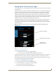
To disconnect the test switch with the XBar:
1.
Click the red crosspoint.
The red crosspoint image turns blue as the test switch is disconnected.
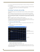
Executing a Test Switch with BCS
We recommend routing a test switch with BCS (Basic Control Structure) commands on the Diagnostics
page (see below) or with the XBar Controller (see page 6).
Note: The Diagnostics page also displays Communication Statistics and provides access to a Telnet
session for controlling the routing system with BCS commands (see page 16).
Note: If you are not familiar with BCS (Basic Control Structure) commands, see the “BCS Protocol
Instruction Manual” on the AMX AutoPatch CD or at www.amx.com.
BCS commands are not case sensitive.
Before executing the test switch, make sure the first two source devices and the first two destination
devices are connected to the input and output connectors exactly as shown in the “AutoPatch Connector
Guide” for your matrix switcher. Depending on the signal and connector type, you may need to attach
more than one input and output for a signal (e.g., a Y/c signal routed over two BNC connectors; one for
Y and one for c).
The following test switch routes Input 1 to Output 2 on Level 0. If the system does not have a VM 0,
use the level indicated on the “AutoPatch Connector Guide.”
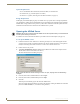
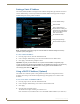
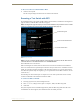
To send a test BCS command:
1.
From any page in the site, click the Diagnostics link.
2. Enter CL0I1O2T (Change Level 0, Input 1 to Output 2, Take) in the BCS string field.
3. Click Send.
The system response for the command displays directly under the BCS string field. When the exact
command that was entered appears, the command has been successfully executed.
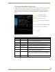
FIG. 4 Diagnostics page
Test BCS string field
Communication Statistics table
Telnet Session button