
Instruction manual

Appendix F – Program Run Disable Mode
212
Instruction Manual – Enova DGX 8/16/32 Digital Media Switchers
Removing the CPU Board and Setting the DIP Switch
Caution: Do not remove the CPU board until you are ready to change the Configuration DIP switch.
Items Required
Phillips #1 screwdriver
ESD wristband and cord with an alligator clip
Note: The following procedure requires that the CPU board be removed, the DIP switch set to
PRD mode, the CPU board reinstalled, and resolution of the communication and/or control problem.
The procedure also includes removal of the CPU board a second time to reset the DIP switch back
to Normal mode.
ESD Warning: To avoid ESD (Electrostatic Discharge) damage to sensitive components, make sure
you are properly grounded before touching any internal Enova DGX materials. Use an ESD
wristband and cord with an alligator clip attached to a good ground source.
To remove an Enova DGX
CPU board and set the DIP switch:
1.
Disconnect both AC power cords. Make sure that none of the power supply LEDs are illuminated.
2. Disconnect all cables connected to the CPU.
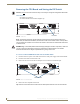
3. Remove the two screws from the CPU faceplate: one each on the far left and far right.
4. Remove the CPU faceplate and set aside.
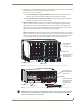
Tip: Removal of the CPU board is easier if the two metal plates under the CPU are removed first.
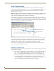
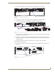
FIG. 114 CPU board
FIG. 115 Remove screws indicated
CPU board
Remove screws