
Instruction manual


Installation and Setup
40
Instruction Manual – Enova DGX 8/16/32 Digital Media Switchers
Program Port and LAN 100/1000 Port
Since the Program port and the LAN 100/1000 port are used in conjunction with each other for NetLinx
system setup, information for cable requirements, LEDs, etc. on each port is given before the setup
information.
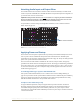
Program Port
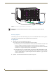
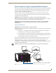
The Enova DGX Switcher’s integrated NetLinx Master is equipped with a low-speed USB connection
labeled “Program.” Use the provided USB mini-AB adapter cable (CA1090-541) to establish a
connection between the Program port on the enclosure and the PC’s USB port. This connection provides
serial-based communication between the integrated Master and NetLinx Studio. This port is useful for
getting and setting the system’s IP address (in NetLinx Studio, open Telnet and enter either
GET IP
<D:P:S> or SET IP <D:P:S>, where D:P:S is Device:Port:System).
Important: The Program port is not recommended for firmware updates or large file transfers.
These more data-intensive operations are better handled via the LAN 100/1000 port connection.
Cable Requirements
USB mini-AB adapter cable (provided) – required to connect an Enova DGX Switcher via its
Program port to a PC.
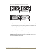
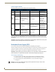
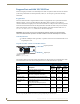
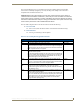
Program Port LEDs – Modes and LED Blink Patterns
The following table lists the modes and the blink patterns for the Program port’s LED indicators which
are associated with each mode. These blink patterns are not evident until the unit is powered.
* Normal is typically off. However, this state may change depending on external inputs.
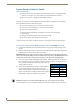
FIG. 24
Program Port LEDs
Modes and LED Blink Patterns
Mode Description
LEDs and Blink Patterns
Status
(Green)
Output
(Red)
Input
(Yellow)
OS Start Starting the operating system (OS). On On On
Boot Integrated Master is booting. On Off On
Contacting DHCP
Server
Integrated Master is contacting a DHCP
server for IP configuration information.
On Off Fast Blink
Unknown DHCP
Server
Integrated Master could not find the DHCP
server.
Fast Blink Off Off
Downloading Boot
Firmware
Downloading Boot firmware to the integrated
Master’s flash memory.
Do not
cycle power during this process.
Fast Blink Fast Blink Fast Blink
No program running Either no program is loaded or the program is
disabled.
On Normal* Normal*
Normal Integrated Master is functioning normally. 1 blink per
second
On
indicates
activity
On
indicates
activity
Program port
Program port LEDs