Instruction Manual Epica DGX 16 Epica DGX 32 Distribution Matrix AutoPatch Matrix Switchers REV B1: 1/25/2011
AMX Limited Warranty and Disclaimer This Limited Warranty and Disclaimer extends only to products purchased directly from AMX or an AMX Authorized Partner which include AMX Dealers, Distributors, VIP’s or other AMX authorized entity.
Contents Contents ESD Warning .......................................................................................................1 Important Safety Information and Instructions ....................................................2 Information et directives de sécurité importantes...............................................3 Notices ................................................................................................................4 Overview and General Specifications ....................
Contents Control Panel Operation................................................................................... 57 Overview ............................................................................................................................... 57 Executing Switches ................................................................................................................ 61 Changing the Virtual Matrix .........................................................................................
Contents Appendix A – EDID Programmer.....................................................................109 EDID Overview .................................................................................................................... 109 Determining the Need for EDID Programming ................................................................... 110 Installing the EDID Programmer ..........................................................................................
Contents iv Epica DGX 16 and Epica DGX 32 Instruction Manual
ESD Warning ESD Warning To avoid ESD (Electrostatic Discharge) damage to sensitive components, make sure you are properly grounded before touching any internal materials. When working with any equipment manufactured with electronic devices, proper ESD grounding procedures must be followed to make sure people, products, and tools are as free of static charges as possible. Grounding straps, conductive smocks, and conductive work mats are specifically designed for this purpose.
Important Safety Information and Instructions Important Safety Information and Instructions When using and installing your AMX AutoPatch product, adhere to the following basic safety precautions. For more information about operating, installing, or servicing your AMX AutoPatch product, see your product documentation. Read and understand all instructions before using and installing AMX AutoPatch products. Use the correct voltage range for your AMX AutoPatch product.
Information et directives de sécurité importantes Information et directives de sécurité importantes Veuillez vous conformer aux directives de sécurité ci-dessous lorsque vous installez et utilisez votre appareil AMX AutoPatch. Pour de plus amples renseignements au sujet de l’installation, du fonctionnement ou de la réparation de votre appareil AMX AutoPatch, veuillez consulter la documentation accompagnant l’appareil.
Notices Notices Copyright Notice AMX© 2011 (Rev B1), all rights reserved. No part of this publication may be reproduced, stored in a retrieval system, or transmitted, in any form or by any means, electronic, mechanical, photocopying, recording, or otherwise, without the prior written permission of AMX.
Notices Trademark Notices AMX®, AutoPatch®, NetLinx®, and SmartScale™ are trademarks of AMX. Windows is a registered trademark of Microsoft Corporation in the United States and other countries. HyperTerminal® is a copyright product of Hilgraeve Inc. 3M®, Desco®, Richmond Technology®, and Plastic Systems® are registered trademarks. Neuron® and LonTalk® are registered trademarks of Echelon. TosLink® is a registered trademark of the Toshiba Corporation.
Notices 6 Epica DGX 16 and Epica DGX 32 Instruction Manual
Overview and General Specifications Overview and General Specifications Applicability Notice The information in this manual applies to the following Epica DGX 16 and 32 enclosures and Epica DGX 16 and 32 pre-engineered systems. It also applies to Epica DGX Input and Output Boards, which can be ordered separately. These boards are compatible in both the Epica DGX 16 and 32. Note: All Epica DGX 16 and 32 enclosures ship with a standard front control panel.
Overview and General Specifications Epica DGX 16 and 32 Input and Output Boards For custom systems and for upgrading pre-engineered systems, the Epica DGX 16 and 32 currently each support two board types: SC Optical and DVI. Each board fills one slot and has four connectors. Within a system, a source connected to any of the input boards can be routed to any destination connected to any of the output boards. For general board information, see page 12 and page 35.
Overview and General Specifications Features of the Epica DGX 16 and 32 (continued) Compatible DGX Fiber Receivers feature SmartScale™ Technology which automatically responds to the display’s declared EDID information and scales the video to the best resolution and video parameters for that display without manual setup.
Overview and General Specifications Front View The enclosure, which is the structural basis of the Epica DGX 16 and 32 Distribution Matrices, can be controlled using the standard front control panel, control software, or an external controller (for additional information on control options, see page 15 and for control panel operation, see page 57). The Power LED indicates the status of the power supplies. LCD Control Dial Input Keys Power Indicator Output Keys Control Keys FIG.
Overview and General Specifications Epica DGX 32 rear view Epica DGX 32 Input boards (up to 8) Output boards (up to 8) Note: Empty input or output board slots (which are numbered for expansion) can be used to upgrade system. Empty input and output board slots Power supplies CPU/Control board Serial number FIG.
Overview and General Specifications Power Supply Units Each of the power supply units on the rear of the enclosure (FIG. 5) has a power receptacle that will accept all major international standard power sources. (US power cords are included with all shipments unless ordered otherwise.) Maximum power specifications are provided on the power supply receptacles. For information on applying power, see page 36.
Overview and General Specifications Epica DGX 32 Input boards Output boards DGX DVI Board DGX SC Optical Board Empty input and output board slots (which are numbered for expansion) can be used to upgrade system FIG. 7 DGX DVI and DGX SC Optical Input and Output Boards Epica DGX 32 enclosures have 16 vertical board slots (8 slots each for input and output boards with four connectors each), allowing for a maximum configuration of 32x32.
Overview and General Specifications Epica DGX 16 General Specifications Specifications Parameter Value Approvals CE, UL, cUL, FCC Class A, RoHS AC Power per Supply 100 VAC to 240 VAC single phase, 50 Hz to 60 Hz Power Consumption (max.) 785 Watts Power Consumption (typical) 210 Watts, fully loaded enclosure Thermal Dissipation (max.) 2679 BTU/hr.
Overview and General Specifications Configuration Information and Control Options The configuration file contains routing and control information for an AMX AutoPatch Routing System. Each system is programmed (configured) at the factory according to customer specifications. Configuration Information As shipped from the factory, the Epica DGX 16 and 32 support Device Discovery.
Overview and General Specifications BCS Serial Control Protocol The Epica DGX 16 and 32 can be controlled with an external serial controller. AMX AutoPatch has developed a command language, BCS* (Basic Control Structure) protocol, for programming control operations and for diagnostic purposes.
Installation and Setup Installation and Setup UL Safety Certifications, Notices, and Recommendations for Laser Products Per UL requirements, make note of the following: The DGX SC Optical Boards comply with IEC Standard: IEC 60825-1, 2001. The boards also comply with 21 CFR 1040.10 and 1040.11 except for deviations pursuant to Laser Notice No. 50, dated June 24, 2007. The DGX SC Optical Output (TX) Boards are CLASS 1 LASER PRODUCTS. The maximum output power of the laser radiation is 4.08 mW.
Installation and Setup Site Recommendations When placing the enclosure, follow the recommendations and precautions in this section to reduce potential installation and operation hazards. Environment Choose a clean, dust free, (preferably) air-conditioned location. Avoid areas with direct sunlight, heat sources, or high levels of EMI (Electromagnetic Interference).
Installation and Setup Circuit Overloading When connecting the equipment to the supply circuits, be aware of the effect that overloading the circuits might have on over-current protection and supply wiring. Reliable Earthing (Grounding) Reliable earthing of rack-mounted equipment should be maintained. If not using a direct connection to the branch circuit (e.g., plugging into a power strip), pay particular attention to supply connections.
Installation and Setup System Setup Options The following table contains eight options for using DGX SC Optical and DGX DVI Boards in an Epica DGX 16 or 32 Matrix Switcher in conjunction with DGX Fiber modules. Note: DGX Fiber modules can also be used in a standalone, end-to-end solution; see the “Instruction Manual – DGX Transmitters & Receivers.
Installation and Setup Safety Recommendations for Laser Products Important: No user serviceable parts are included inside an AMX AutoPatch product; service should only be done by qualified personnel. Caution - Use of controls or adjustments or performance of procedures other than those specified herein may result in hazardous radiation exposure. Exercise caution when installing DGX products to avoid direct eye exposure to invisible laser radiation.
Installation and Setup 3. If applicable – For multiple-enclosure systems, link them according to the instructions provided (see page 24). Caution: On systems with SC fiber connectors, we recommend using the provided cable management bars or some other type of cable management system to avoid damage to the fiber cables. 4. Recommended for DGX SC Optical Boards – Attach the provided cable management bars to the input and output boards (see page 23). 5.
Installation and Setup Attaching Cable Management Bars AMX AutoPatch cable management bars are provided for DGX SC Optical Input and Output Boards. Caution: Do not severely bend or kink the SC fiber cable. Irreversible damage can occur. Refer to the physical limitations (bend radius) specified for the cable by the manufacturer. The bend radius for AMX SC terminated fiber cables is 2 inches (5 cm). To install cable management bars: 1.
Installation and Setup Linking Enclosures Epica DGX 16 and 32 enclosures can link to each other or to most other types of AMX AutoPatch Distribution Matrices (see the tables below). Important: The shipping boxes each have a bright yellow/green sticker that states that the unit (enclosure) is part of a multiple-enclosure system and must be installed with the same serial numbers. The Epica DGX 16 and 32 enclosures use two Ethernet (10/Base-T) ports on their CPUs to link to other enclosures.
Installation and Setup Link Cables and Equipment List RJ-45 Crossover Cable: use for direct linking between two or more Epica DGX 16 or 32 enclosures or between an Epica DGX 16 or 32 and any other 10Base-T enclosure; also used to connect 10Base-T (RJ-45) enclosures to a Media Converter or to a Multi-Port Switch. The cable is wired to TIA/EIA-568-A on one end and TIA/EIA-568-B on the other end.
Installation and Setup 2. Insert the connector on the other end of the RJ-45 cable into the Enc Link (RJ-45) port on the second enclosure (FIG. 14). RJ-45 cable Max. 100 ft. (30.5 m) FIG. 14 Epica DGX 32 linked to an Optima using RJ-45 cable When power is applied, the Ethernet connector LEDs illuminate indicating communication status (see above).
Installation and Setup 9. Add a 50-ohm termination connector to the open end of the T-connector on the last enclosure of the cable run. The total length of all cables between the Media Converter and the last enclosure in a daisy chain cannot exceed 10 ft. (3.05 m). 50-ohm termination connector RJ-45 cable Max. 100 ft. (30.5 m) RG-58 coax cable Max. 10 ft. (3.05 m) Media Converter FIG.
Installation and Setup 2. Insert the open end of the RJ-45 cable into the Multi-Port Switch. 3. Repeat Steps 1 and 2 using RJ-45 straight-through patch cable for other types of enclosures with 10Base-T (RJ-45) ports.* Go to page 28 for enclosures with 10Base-2 (BNC) ports. * Applies when linking an Epica DGX 144, Epica DG, Optima, Optima SD, or a Precis SD to a Multi-Port Switch. The total length of all cables between the Media Converter and the last enclosure in a daisy chain cannot exceed 10 ft. (3.
Installation and Setup Attaching External Controllers Epica DGX 16 and 32 enclosures can be controlled externally by attaching a control device that uses one of the communication protocols listed below: BCS (Serial) – ASCII sent over a null modem serial cable via the serial port BCS (USB) – ASCII sent over a USB cable via the USB (mini-B) port XNNet – AMX AutoPatch protocol via the serial port TCP/IP – TCP/IP sent over an RJ-45 cable via the TCP/IP port for establishing an NXB-AP-1000 connection to a LAN I
Installation and Setup Connecting Serial Controllers An external serial controller is any device that can send and receive ASCII code over an RS-232 (null modem) serial cable attached to the serial port (DB-9) on the enclosure’s CPU. (The USB port can also be used by creating a virtual Com port; see page 32.) PCs are common serial controllers. Once a PC is attached to the Epica DGX 16 or 32, the system can be controlled by running APControl software on the attached PC (see the AMX AutoPatch CD).
Installation and Setup 4. Setup and run the desired method of control: AMX Controller – For control programming information, see the instruction manual for the specific interface APControl 3.0 – Install and open the program (located on the AMX AutoPatch CD). Follow the setup wizard. Manually create the VM (virtual matrix) and specify the number of inputs and outputs. Open the APControl Launchbar. From the Launchbar menu, select Views / CrossBar and click the crosspoints to execute switches.
Installation and Setup Connecting Serial Controller to USB Port Controlling an Epica DGX 16 or 32 using a USB connection requires the creation of a virtual Com port. Once created, the virtual Com port is used as if it were a standard serial connection and can connect to a control application (such as, APControl 3.0) or to a terminal emulation program (e.g., Windows® HyperTerminal) for BCS control. Important: You must have adequate rights to install USB device drivers to the PC.
Installation and Setup The Found New Hardware Wizard opens with the default selected to automatically install the software. (The dialog boxes may differ slightly from those shown, depending on the operating system for the PC.) 4. Insert the AMX AutoPatch CD into the PC’s CD holder. 5. Click Next. 6. Click Finish when prompted to close the wizard.
Installation and Setup 2. If the port specifies the Com number, go to Step 4. If the port does not specify the Com number, right-click AutoPatch USB Bridge and select Properties and complete all remaining steps. Assigned port number (if not displayed, complete all remaining steps) 3. In the AutoPatch USB Bridge Properties dialog box, select the General tab. 4. Make note of the Com port assigned to the AutoPatch USB Bridge.
Installation and Setup Important: If power is cycled on the enclosure, the USB connection must be reestablished. Remove the USB cable and close the software application in use. Then reconnect the USB cable to the same USB connector used previously and reopen the communication software. Attaching Input and Output Cables Input and output connectors are the attachment points for source and destination devices that connect to the system.
Installation and Setup Input and Output Signal Cables When attaching input and output signal cables in a multiple-enclosure system, check the system and enclosure numbers are on the rear of the Epica DGX 16 or 32 (if not on the rear, the numbers are on the side). The system was programmed at the factory to operate only as a specifically configured system. If AMX AutoPatch cable management bars are used, they are installed before attaching cables (see page 23).
Installation and Setup Power-Up Sequence Caution: Each power supply has a small toggle switch to the left of its LEDs that controls internal power and must remain flipped to the right for the system to operate. Do not flip this switch to the left. The following instructions start with attaching only two source and destination devices for the purpose of executing a test switch. To apply power: 1.
Installation and Setup Indicator Lights at Startup When the enclosure powers up, the indicator LEDs respond as follows: Epica DGX 16 and 32 LED Indicators LED Front Rear – Power Supply Indicates Power Normal Display System power Constant green AC Power ( ) AC power present Constant green Not illuminated: AC failure DC Power ( ) DC power present Constant green Not illuminated: DC failure Not illuminated Amber: power supply is over temperature Temperature ( ) Power supply temperature Rear
Installation and Setup AMX Control Devices The Epica DGX 16 and 32 are compatible with a number of AMX control devices. For control programming information, see the instruction manual for the specific interface. APControl 3.0.1 If you are using APControl 3.0.1, install and open the program. Follow the directions in the setup wizard. Follow the setup wizard. Manually create the VM (virtual matrix) and specify the number of inputs and outputs. Open the APControl Launchbar.
Installation and Setup Executing a Test Switch For new system installations, we recommend executing a test switch to verify the system is working properly before attaching all inputs and outputs. Aside from having signal cables and a controller attached, the system is ready to execute switches when it ships from the factory.
Installation and Setup When using HyperTerminal, command characters are entered and sent to the enclosure’s CPU (the command characters appear in HyperTerminal when the enclosure responds). When all of the entered characters appear in HyperTerminal, the command has been successfully executed. Levels in BCS commands are the equivalent of virtual matrices for switching purposes. The following test switch routes Input 1 to Output 2 on Level 0 (VM 0, the default virtual matrix). To execute the test switch: 1.
Installation and Setup Technical Support Before contacting technical support with a question, please consult this manual. If you still have questions, contact your AMX representative or technical support. Have your system’s serial number ready (the number is normally located on the rear of the enclosure). We recommend recording your system’s serial number in an easily accessible location. AMX Contact Information 3000 Research Drive, Richardson, TX 75082 800.222.0193 469.624.8000 Fax 469.624.
Installation and Setup RJ-45 Cable Requirements Cable Requirements LAN Connection – an RJ-45 link cable (either crossover or straight-through) is required to connect an Epica DGX 16 or 32 enclosure to a LAN. TCP/IP Port and Indicator LEDs The TCP/IP port, which provides the NXB-AP-1000 connection, is located on the rear of the enclosure on the right-hand side of the CPU (FIG. 27).
Installation and Setup To connect an Epica DGX 16 or 32 to a LAN: Important: In order to use the NXB-AP-1000 connection, the Epica DGX 16 or 32 must establish an active connection to a LAN (network). Connecting the TCP/IP port on the Epica DGX 16 or 32 to a PC will not work. 1. Complete the installation of the Epica DGX 16 or 32 system (see page 21) including power up of the system. 2. Insert one end of the RJ-45 link cable into the TCP/IP port on the enclosure. 3.
Installation and Setup To determine the IP address by accessing the NXB-AP-1000 via Zero-Config: 1. In NetLinx Studio (v3.0 or higher), left-click the Zero-Config tab on the Workspace Bar to open the tab. NXB-AP-1000 interface’s system name IP address for NXB-AP-1000 interface Zero-Config tab FIG. 29 NetLinx Studio showing the Zero-Config tab and the IP address for an NXB-AP-1000 interface 2.
Installation and Setup NXB-AP-1000 Troubleshooting Check the following: All power, signal, and link connections on all of the equipment. LED indicators for the TCP/IP (RJ-45) connector on the rear of the Epica DGX 16 or 32. If the LED indicators are not illuminated, check the cable type to make sure it meets cable requirements (see page 43). LED indicators on the NetLinx Master. Ping the system, i.e., at the DOS prompt enter: ping XXX.XXX.XXX.XXX (where XXX.XXX.XXX.
Epica DGX SC Optical Boards Epica DGX SC Optical Boards Applicability Notice This chapter pertains to the following Epica DGX SC Optical Boards: FG1056-500 FG1056-510 Input board Output board FIG. 30 Epica DGX SC Optical Boards, shown in an Epica DGX 32 Epica DGX 16 Epica DGX 16 enclosures are built to hold up to eight DGX SC Optical Boards with four inputs or outputs per board.
Epica DGX SC Optical Boards Specifications Epica DGX SC Optical Boards Applies to input board FG1056-500 and output board FG1056-510. Compatible AMX AutoPatch DGX Fiber modules: FG1010-200-01 – AVB-TX-DGX-HD15-SC Fiber FG1010-210-01 – AVB-TX-DGX-DVI-SC Fiber FG1010-400-01 – AVB-RX-DGX-SC Fiber-HD15 FG1010-410-01 – AVB-RX-DGX-SC Fiber-DVI Note: Either Transmitter (TX) module can be used in conjunction with either Receiver (RX) module.
Epica DGX SC Optical Boards System Setup with DGX Modules DGX SC Optical Input and Output Boards are used in conjunction with AMX AutoPatch DGX Fiber TX and RX modules. Compatible DGX Fiber modules are listed on page 48. System setup options are listed in a table on page 20. For module installation details, see the module’s Quick Start Guide or Installation Manual. When the modules are installed, image adjustment and EDID scaling is automatically applied.
Epica DGX SC Optical Boards Safety Recommendations for Laser Products Important: No user serviceable parts are included inside an AMX AutoPatch product; service should only be done by qualified personnel. Caution - Use of controls or adjustments or performance of procedures other than those specified herein may result in hazardous radiation exposure. Exercise caution when installing DGX products to avoid direct eye exposure to invisible laser radiation.
Epica DGX SC Optical Boards 4. Insert the fiber cable connector into the input and output SC fiber receptacles (FIG. 32). Epica DGX 32 Epica DGX 16 Tie cable to cable management bar far enough below connector to allow for manufacturer’s recommended bend radius FIG. 32 Fasten cables onto input and output connectors (shown with cable management bar) 5. Tie the SC fiber cable to the cable management bar far enough below the connector to allow for the manufacturer’s recommended bend radius.
Epica DGX SC Optical Boards 52 Epica DGX 16 and Epica DGX 32 Instruction Manual
Epica DGX DVI Boards Epica DGX DVI Boards Applicability Notice This chapter pertains to the following Epica DGX DVI (Digital Visual Interface) Boards: FG1056-520 FG1056-530 Input board Output board FIG. 33 Epica DGX DVI Input and Output Boards Epica DGX 16 Epica DGX 16 enclosures are built to hold up to eight DGX DVI Boards with four inputs or outputs per board.
Epica DGX DVI Boards Specifications Epica DGX DVI Applies to input board FG1056-520 and output board FG1056-530. Digital Video – DVI Specifications Parameter Value Signal Type DVI-D (single link) Resolution Support 640x480 @ 60 Hz up to 1920x1200 @ 60 Hz Interlaced Resolution Support 1080i 60, 59.94, 50 (fields per second) 576i 100, 50 (fields per second) 480i 60 (fields per second) Data Rate (max.) 4.95 Gbps Pixel Clock (max.
Epica DGX DVI Boards Attaching Cables To connect DVI inputs and outputs: 1. Fasten the DVI-I (or DVI-D) connectors on the cable ends onto the DVI-I receptacles on the boards. (For DVI pinout information, see below.) DVI-I connector FIG. 34 Fasten cables onto input and output connectors DVI Pinout Pinout information for the DVI-I connector on the DGX DVI Input and Output Boards is provided in the chart in FIG. 35. DVI-I Pinout 1. Data 2- 9. Data 1- 17. Data 0- C1. No connect 2. Data 2+ 10.
Epica DGX DVI Boards 56 Epica DGX 16 and Epica DGX 32 Instruction Manual
Control Panel Operation Control Panel Operation Overview The Epica DGX 16 and 32 Control Panels (standard on all enclosures) are used for controlling system switches and system attributes. Both control panels function the same, but have input and output key support respective to their size. Note: AMX AutoPatch software can also be used to control a system; for more information on control options, see page 15.
Control Panel Operation Control Keys and Dial (continued) Take Key The Take Key functions much like the Enter Key on a computer keyboard. Pressing the Take Key instructs the system to execute or disconnect a switch. Prior to pressing the Take Key, the individual operation component(s) are selected by pressing the appropriate key(s). Control Dial The Control Dial scrolls through the menu options and adjusts values.
Control Panel Operation Menus and Modes The Function menu and its submenus access the modes and functions used to control the system. The modes are Change, Virtual Matrix, Status, Disconnect, Setup Options, Lock Panel, Global Preset, and Local Preset. While in a mode, the same command can be repeated, without having to return to the Function menu to reselect the mode, e.g., executing more than one local preset. Use the Control Dial and Select Key to navigate the Function menu, and submenus.
Control Panel Operation Local Preset Selecting Local Preset accesses the list of local presets that can be executed (see page 67). Local Preset will only appear as an option on the Function menu if local presets have been defined in XNConnect for the selected virtual matrix. Epica DGX 16 and 32 Control Panel operation consists of the following four basic tasks: Choosing a mode, submenu, or list: press the Function Key to access the Function menu.
Control Panel Operation Executing Switches A switch is an active connection between an input (source) device and one or more output (destination) devices. The signals routed in a switching operation are individual signals or groups of individual signals coming through the connectors on the rear of an enclosure. You can execute switches from the Control Panel using the steps below or by defining and executing a global preset (see page 65) or by executing a local preset (see page 67).
Control Panel Operation 2. Press the Select Key to choose Change. The system is in Change Mode (the available Input and Output Keys turn blue). Virtual matrix 3. Press Input Key 1. Input Key 1 flashes indicating that it is ready to switch. (Any outputs currently connected to Input 1 will turn white.) 4. Press Output Key 1. Output Key 1 illuminates indicating that it is ready to accept the switch. 5. Press the Take Key. Input 1 switches to Output 1, and the keys turn blue.
Control Panel Operation 5. Press the Select Key to enter your selection. The display returns to the top of the V.Matrix submenu. VM 2 “Custom” becomes the new virtual matrix used for all operations. Newly selected virtual matrix 6. Press the Function Key to return to the Function menu. The system is ready to execute operations on VM 2.
Control Panel Operation 3. Press the Select Key. The system is in Disconnect Mode (all the available Input and Output Keys turn blue). 4. Press Input Keys 1 and 3 and Output Key 9. The keys turn white indicating that they are selected. Virtual matrix 5. Press the Take Key. Inputs 1 and 3 (and all outputs connected to them) and Output 9 are disconnected as soon as the Take Key is pressed and the keys turn blue. 6. Make additional disconnects. Or press the Function Key to return to the Function menu.
Control Panel Operation 5. Select another signal to verify. Or press the Function Key to return to the Function menu. Defining and Executing Global Presets Global presets are predefined sets of switches that can easily be executed at one time. A global preset number can be assigned to a routing state during runtime and stored by the system, allowing you to replicate an entire system state. (The system state includes any special settings and all signal routings.
Control Panel Operation 6. Scroll with the Control Dial until Global Preset 3 appears. 7. Press either the Select Key or the Take Key. 8. Wait approximately ten seconds for the system to store the global preset setting. The current routing state can now be recalled as Global Preset 3, and the system returns to the Global Preset submenu. 9. Press the Function Key to return to the Function menu. Executing Global Presets To execute a global preset: 1. Press the Function Key.
Control Panel Operation Executing Local Presets A local preset is a predetermined set of switches on a particular virtual matrix that are routed simultaneously. They are stored in each enclosure’s configuration file and can be executed at any time. Local Preset will not appear as a submenu option in the Function menu if local presets have not already been defined. In addition, they will not appear if the system is on a virtual matrix that does not have local presets.
Control Panel Operation Adjusting Audio Important: This section of the manual does not apply to embedded audio transmitted over SC fiber cables. Some audio boards in AMX AutoPatch Distribution Matrices offer optional volume control and digital input gain adjustment features. If your Epica DGX 16 or 32 system is linked to an enclosure that contains these boards, output volume or digital input gain can be adjusted using either the Control Panel or BCS commands sent through a serial controller.
Control Panel Operation 3. Press the Select Key. The Adjust Audio submenu appears. 4. Press the Select Key again to choose Output Volume. The Control Panel is in Output Volume Mode (all Input Keys are turned off, and the available Output Keys turn blue). Current VM 5. Press the Output Key that corresponds to the output to be adjusted. The Adjust Volume Screen appears, displaying the volume range of the audio board and the current volume setting for the selected output.
Control Panel Operation Muting and Un-Muting Outputs This feature works only for enclosures that support volume control linked to the Epica DGX 16 or 32. Note: The mute/un-mute option applies to output volume only and is not available for input gain. To mute an output: 1. Press the Function Key. The Function menu appears. 2. Locate Adjust Audio by scrolling with the Control Dial. 3. Press the Select Key to enter the selection. The Adjust Audio submenu appears. 4. Scroll to Mute/Unmute. 5.
Control Panel Operation Typical uses for input gain adjustment include switching consumer and professional grade audio equipment (whose levels can vary noticeably) in the same matrix switcher. Input gain adjustment is also used for equalizing amplitudes between balanced and unbalanced source inputs. To adjust input gain (including adjusting input gain to equalize input levels): 1. If adjusting input gain to equalize input levels – Route a source (input) to the desired destination (output). 2.
Control Panel Operation Locking and Unlocking Locking the Epica DGX 16 or 32 Control Panel prohibits access to the system and can prevent accidental switching. While the panel is locked, BCS commands still work; however, they cannot be used to unlock the panel. The panel remains locked if the power is cycled. The password used to lock and unlock the panel consists of a sequence of five input keys. The factory default password is the first five Input Keys (1-2-3-4-5).
Control Panel Operation Unlocking the Control Panel When the panel is locked and you press any key, the Unlock Panel Screen appears. You have ten (10) seconds to enter the password or the Control Panel remains locked. If you wait longer than 10 seconds, press any key again before entering the password. If you enter the wrong password while attempting to unlock the Control Panel, an invalid password message appears and the Cancel Key flashes.
Control Panel Operation 2. Locate Setup Options by scrolling with the Control Dial. 3. Press the Select Key. The Setup Options submenu appears. Locate Software Version by scrolling with the Control Dial. 4. Press the Select Key again to choose Software Version. The Software Version Screen appears. Version number 5. Scroll with the Control Dial to see additional Software Version information. 6. Press the Cancel Key to return to the Setup Options submenu.
Control Panel Operation 4. Scroll to Default VM. Press the Select Key. The Default VM list appears. Current default virtual matrix 5. Scroll to 2:Custom. 6. Press the Select Key. The display returns to the top of the Setup Options submenu. 7. Cycle power to implement VM 2 as the default virtual matrix. Or change the virtual matrix (see page 62) to immediately execute operations on the new default virtual matrix without cycling power.
Control Panel Operation Setting the Password The Epica DGX 16 and 32 Control Panel’s default password is “1 2 3 4 5” entered using the first five input keys. A new password can be set using any combination of five of the Input Keys 1 through 8 when the LCD displays “Enter New PWD” (Step 5 in the following procedure). In the Change Password Mode (selected in Step 4), the keys available to use in a password will illuminate blue.
Control Panel Operation These The LCD displays Reenter New PWD. 6. Re-enter the new password. If the re-entered password matches, the system accepts it as the new password, and the LCD displays Password Reset. Press the Take Key and go to Step 7. Or If the re-entered password does not match, the LCD displays Invalid Password. Press the Cancel Key to return to Enter New PWD screen and repeat Steps 5 and 6. 7.
Control Panel Operation For the following instructions, open HyperTerminal (or other terminal emulation program) on a PC; see page 29. To enable error code reporting: 1. Enter $ERR=1! The system responds with a V. Note: If the power is cycled after this procedure, you will need to enable error code reporting again. To turn off error code reporting: 1. Enter $ERR=0! Most Common System Error Codes Error Codes Name Meaning Basic Troubleshooting Strategies • Resend the command.
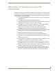
NXB-AP-1000 Interface – Initial Setup by Network Admin NXB-AP-1000 Interface – Initial Setup by Network Admin Overview Applicability Notice The information in this chapter covers the NXB-AP-1000 interface v1.0.0.1. Important: If you have not already done so, see the installation instructions for the TCP/IP to LAN connection (page 42).
NXB-AP-1000 Interface – Initial Setup by Network Admin System Requirements Web browser (Internet Explorer 7.0 or Firefox 3.6.8, etc.) JRE v1.4.x or greater (Java Plug-in for the XBar Controller) Note: The instructions in this chapter assume that the Epica DGX 16 or 32 is connected to a LAN and receiving power.
NXB-AP-1000 Interface – Initial Setup by Network Admin Opening the NXB-AP-1000 Interface Caution: We strongly recommend that the NXB-AP-1000 interface site be placed inside your network firewall and that system security be turned on. To open the NXB-AP-1000 interface: 1. From the NetLinx Studio Zero-Config tab – Double-click on “NIB IP-Bridge Interface” or right-click and select one of the launch browser options.
NXB-AP-1000 Interface – Initial Setup by Network Admin Navigating the NXB-AP-1000 Interface The NXB-AP-1000 interface has two drop down menus: IP Control and Admin. These menus access all the control, configuration, preferences, and settings pages in the interface. The menu options are shown in FIG. 42 and FIG. 43. In addition, some pages have tab options as well (see FIG. 45 on page 84). IP Control Menu - Options for the IP Control Pages in the Interface FIG.
NXB-AP-1000 Interface – Initial Setup by Network Admin Setting a Static IP Address The current IP address is displayed on the IP Settings page. FIG. 44 IP Settings page Note: When the DHCP setting is selected and you power the system down and then power back up, the DHCP server will reassign the IP address, which may or may not be the same address it assigned previously. Setting a static IP address prevents the possibility of the IP address changing at power up. To enter a static IP address: 1.
NXB-AP-1000 Interface – Initial Setup by Network Admin Connecting to a NetLinx Master To establish communication between an Epica DGX 16 or 32 and a NetLinx Master: 1. From the Admin drop down menu, select Master Connection. FIG. 45 Master Connection page 2. Optional – Under Connection Mode, select one of the options (default = TCP/IP URL). 3. Under Mode Settings, enter the Master’s IP/URL in the Master IP/URL text field.
NXB-AP-1000 Interface – Initial Setup by Network Admin Handling Security Issues From the NXB-AP-1000 interface, you can enable or disable security access to web server control of the Epica DGX 16 or 32 system. If tight security is required, we recommend that the following security measures be followed: Enable/Disable the security settings and login information as part of the initial setup (see below). Place the server site inside your network firewall.
NXB-AP-1000 Interface – Initial Setup by Network Admin Note: If you enable a Security Setting and then click Accept without specifying Login Information, the login defaults apply (see below). Setting Login Information The Login Information settings are required only if one or more of the security settings are enabled. To set the login information: 1. Username – Enter the Username that will be required to log into the system if security is enabled. The default Username is administrator. 2.
NXB-AP-1000 Interface – Initial Setup by Network Admin Executing a Test Switch with the XBar Controller The NXB-AP-1000 interface includes access to the XBar Controller for executing and disconnecting switches on an AMX AutoPatch Routing System. Before executing a test switch, make sure the first source device and the first destination device are connected to the input and output connectors as indicated in the “AutoPatch Connector Guide” that shipped with the system.
NXB-AP-1000 Interface – Initial Setup by Network Admin Customizing the XBar Controller The NXB-AP-1000 interface provides control for an AMX AutoPatch Routing System with the XBar Controller. The XBar displays crosspoints for the input and output channels. Options for customizing the XBar are: Setting the virtual matrix (VM) for XBar control Setting the size of the XBar window The settings for these options are located on the same page (accessible from IP Control drop down menu). FIG.
NXB-AP-1000 Interface – Initial Setup by Network Admin Executing and Disconnecting Switches The NXB-AP-1000 interface provides the XBar Controller for executing and disconnecting switches on an AMX AutoPatch Routing System. For complete information, see the “NXB-AP-1000 Interface – Controlling an Epica DGX 16 or 32” chapter on page 95.
NXB-AP-1000 Interface – Initial Setup by Network Admin Clock Manager - Daylight Savings (only available if Network Time is selected) To adjust Daylight Savings settings in the Clock Manager: 1. From the Admin drop down menu, select Clock Manager (or select Mode from the Clock Manager submenu). 2. Under Time Sync, select Network Time and click Accept. 3. Click the Daylight Savings tab. FIG. 49 Daylight Savings Manager page 4. Modify any of the settings on the Daylight Savings page and click Accept.
NXB-AP-1000 Interface – Initial Setup by Network Admin DoD Security Mode Epica DGX 16 and 32 matrix switchers provide a DoD Security mode (for security profile settings, see the table on page 93). Important: When DoD Security mode is “on” a BCS tunnel is available; however, the NXB-AP-1000 interface is unavailable. To enable DoD Security mode for an Epica DGX 16 or 32: 1. Insert one end of an RJ-45 cable into a network card on a PC. 2.
NXB-AP-1000 Interface – Initial Setup by Network Admin three security profile settings table To disable DoD Security mode for an Epica DGX 16 or 32: 1. Insert one end of an RJ-45 cable into a network card on a PC. 2. Insert the other end of the cable into the TCP/IP port on the enclosure. 3. Open an SSH terminal utility (e.g., Putty) and connect to the IP address of the NXB-AP-1000. SSH utilities require a username and password to login (see “Important” note on previous page). 4.
NXB-AP-1000 Interface – Initial Setup by Network Admin Set Security Profile Settings table w/DoD The three security profile terminal command settings are described in the table below. Set Security Profile Settings Setting Description None (default) • No security is enabled and all interfaces are available, including HTTP, HTTPS, Telnet, SSH, and FTP. • Logins are not required on the NXB-AP-1000 interface or Telnet. • This is the default from-the-factory configuration.
NXB-AP-1000 Interface – Initial Setup by Network Admin 94 Epica DGX 16 and Epica DGX 32 Instruction Manual
NXB-AP-1000 Interface – Controlling an Epica DGX 16 or 32 NXB-AP-1000 Interface – Controlling an Epica DGX 16 or 32 XBar Controller Overview The NXB-AP-1000 Interface includes the option of using an XBar Controller which allows for remote control of Epica DGX 16 and 32 Matrix Switchers using PC-based Internet browsing software. Opening the XBar Controller The XBar Controller can be accessed from any page in the NXB-AP-1000 Interface by opening the IP Control drop down menu and selecting Controller.
NXB-AP-1000 Interface – Controlling an Epica DGX 16 or 32 Note: Multiple independent AMX AutoPatch Routing Systems (each with server connection) can be controlled from a single PC. Each NXB-AP-1000 Interface can be assigned a unique IP address. The individual addresses can then be entered as needed in the browser. The IP address displays at the top of the XBar Controller, indicating which XBar you are using.
NXB-AP-1000 Interface – Controlling an Epica DGX 16 or 32 To execute or disconnect switches on the XBar: 1. Access the XBar using the instructions on page 95. The XBar opens. 2. Optional (to change the virtual matrix) – Click the VM title block in the upper left corner. The VM Selection Pad dialog box opens. Select VM from list VM List From the VM drop down list, select the new virtual matrix. Close the VM Selection Pad. 3. Click a blue (inactive) crosspoint to execute a switch.
NXB-AP-1000 Interface – Controlling an Epica DGX 16 or 32 98 Epica DGX 16 and Epica DGX 32 Instruction Manual
NXB-AP-1000 Interface – Additional Info for Network Admin NXB-AP-1000 Interface – Additional Info for Network Admin This chapter contains information on upgrading firmware (see below), embedding the XBar applet (see page 100), and changing the proxy setting (see page 101). Upgrading Firmware Firmware upgrades for the NXB-AP-1000 Interface on the Epica DGX 16 and 32 are handled via NetLinx Studio using .KIT files. Before You Start Verify you have the latest version of NetLinx Studio on your PC.
NXB-AP-1000 Interface – Additional Info for Network Admin Embedding the XBar Applet The XBar applet can be embedded in a custom website by using the applet tag shown below. Make any of the following adjustments to the code to fit your particular system’s requirements. Replace the code base value with the IP address for your system.
NXB-AP-1000 Interface – Additional Info for Network Admin Changing the Proxy Setting If the NXB-AP-1000 Interface does not open during setup, try the following troubleshooting strategies: Check all power, signal, and link connections on all of the equipment. Check LED indicators for the TCP/IP (RJ-45) connector on the Epica DGX 16 or 32. If the LED indicators are not illuminated, check the cable type to make sure it meets cable requirements (see page 43). Check LED indicators on the NetLinx Master.
NXB-AP-1000 Interface – Additional Info for Network Admin 2. Select the Connections tab. 3. Click LAN Settings. The Local Area Network (LAN) Settings dialog box opens. If the Proxy server box is checked, go to Step 4. If the Proxy server box is not checked, check it before going to Step 4.
NXB-AP-1000 Interface – Additional Info for Network Admin 4. Click Advanced. The Proxy Settings dialog box opens. Enter NXB-AP-1000 Interface IP address 5. In the Exceptions field, enter the appropriate NXB-AP-1000 Interface IP address (see page 80). 6. Click OK to exit each of the dialog boxes used in these steps.
NXB-AP-1000 Interface – Additional Info for Network Admin 104 Epica DGX 16 and Epica DGX 32 Instruction Manual
Epica DGX 16/32 NetLinx Programming Epica DGX 16/32 NetLinx Programming Overview The Epica DGX 16/32 recognizes NetLinx SEND_COMMANDs with embedded BCS commands. Use NetLinx Studio (Version 3 or higher is required) to send these commands to the Epica DGX 16/32, or use these commands in standard compiled NetLinx Programming code running on a NetLinx Master. Use the commands and ports specified in this chapter.
Epica DGX 16/32 NetLinx Programming SEND_COMMANDs For the Epica DGX 16/32, SEND_COMMANDs carrying basic BCS commands for control operations (only) can be sent to Port 2, and SEND_COMMANDs carrying diagnostic or auxiliary BCS commands can be sent to Port 3. The first table shows three SEND_COMMANDs with embedded basic BCS commands that can be sent to Port 2. The second table shows two SEND_COMMANDs with embedded diagnostic and auxiliary BCS commands that can be sent to Port 3.
Epica DGX 16/32 NetLinx Programming Epica DGX 16/32 SEND_COMMANDs - Basic BCS Commands (continued) " 'SLIT' " (input status) or " 'SLOT' " (output status) Returns connection status. (To verify status on the default level, omit L.) Syntax: SEND_COMMAND ,"'SLIT'" or SEND_COMMAND ,"'SLOT'" Note that the "Device" number is assigned by the NetLinx Master.
Epica DGX 16/32 NetLinx Programming 108 Epica DGX 16 and Epica DGX 32 Instruction Manual
Appendix A – EDID Programmer Appendix A – EDID Programmer EDID Programmer software is provided for re-programming the EDID EEPROM chips on Epica DGX DVI Input Boards if necessary. This software is available on the AMX AutoPatch CD or at www.amx.com.
Appendix A – EDID Programmer Important: Any analysis or editing of the EDID data necessary to support the equipment specific to your installation will need to be done separately prior to using the EDID Programmer. A variety of freeware tools can be found on the web to help with these tasks. Keep in mind that the EDID information for some equipment may not be compatible with the remaining equipment even with programming. In those cases, the signals will have limited routing options.
Appendix A – EDID Programmer To install EDID Programmer software: 1. Locate and open the installer on the AMX AutoPatch CD or at www.amx.com. 2. Follow the directions in the wizard. Reading and Saving EDID Data from a Destination Device Tip: The Save button in the EDID Programmer can be used to save the EDID information as an .edid file, which can be opened as a text file (click on the Open button) and edited or opened and written to an input (click the Write button).
Appendix A – EDID Programmer 8. Disconnect the DVI cable from the PC and from the destination device. Using Cable Adapters If your laptop has an HD-15 (VGA) port, you can use a DVI-to-VGA cable to connect the laptop’s HD-15 video port to a DVI cable attached to a destination device’s DVI port.
Appendix A – EDID Programmer 10. Save the board’s EDID default as a backup (assumes the board has factory default EDID programming). Click the Refresh Display List button. Select the device. Click the Read button. Click the Save button (select location, enter file name, and click Save). 11. Click the Open button to select the .edid file to be written to the DVI input connector. 12. Click the Write button to write the EDID information to the DVI input connector. 13.
Appendix A – EDID Programmer 114 Epica DGX 16 and Epica DGX 32 Instruction Manual
Appendix B – Managing Configuration Files Appendix B – Managing Configuration Files Applicability Notice This appendix applies to XNConnect version 2.10.0. XNConnect’s version information is found under its Help menu. Version 2.10.0 supports full Device Discovery through AMX’s AutoPatch Duet module.
Appendix B – Managing Configuration Files Overview Caution: Unless you need to reload the .xcl configuration file or modify your system's configuration from the original specifications, you will not need to use XNConnect. We recommend making a copy of the current file every time the file is modified. XNConnect can be used to modify a system’s configuration information which contains routing and control information. XNConnect is provided on the AMX AutoPatch CD shipped with each system.
Appendix B – Managing Configuration Files AMX AutoPatch CD Information If you cannot locate the AMX AutoPatch CD that shipped with your system and your AMX account has the required permissions, you can download the newest version of XNConnect from www.amx.com. An INI file Updater for updating XNConnect is available on the AMX website under Tech Center \ AutoPatch Tools; an account is not required. If you need an .
Appendix B – Managing Configuration Files To launch XNConnect: 1. From the Start menu, select Programs. 2. Select AutoPatch Applications (or other file group you specified during the installation). 3. Select the XNConnect folder. 4. Select XNConnect. The XNConnect program opens. Getting Started dialog box When XNConnect is open, two options are available for accessing the information: Discover the system (recommended).
Appendix B – Managing Configuration Files 5. If applicable – For a serial port other than Com 1 (default), open the Communication menu again, select Change Comm Settings. Check the settings for the selected port and adjust if necessary (the default is Com 1, baud rate 9600). 6. Optional – Click the Test button to verify that communication has been established with the enclosure. Click OK. 7. From the File menu, select Discover System (the discovery may take a few minutes). 8.
Appendix B – Managing Configuration Files Navigating the Interface XNConnect displays configuration information in two panes. The graphics are located in the left pane, and the properties of the currently selected graphic are in the right pane. At the top of the left pane are two tabs, Hardware and Virtual Matrices, for accessing the Hardware and Virtual Matrices views (see below).
Appendix B – Managing Configuration Files Modifying an .xcl Configuration File Modifying an .xcl configuration file with XNConnect involves entering information in a field or in a series of dialog boxes. A brief look at the contents in the Help file provides a quick overview of the possible modifications. This section provides instructions for two common tasks: setting the Control Panel password and creating local presets. For complete coverage of configuration related tasks, see the XNConnect Help file.
Appendix B – Managing Configuration Files Creating Local Presets A local preset is a predetermined collection of switches on the same virtual matrix to be routed simultaneously. Executing a local preset affects only those inputs and outputs specified, not the whole system. Local presets are defined using XNConnect and can be executed using the Control Panel or using BCS commands entered as part of a macro in APControl 3.0 or entered in a terminal emulation program.
Appendix B – Managing Configuration Files 6. For the first switch, click the source channel (input) and one or more destination channels (outputs). Select multiple destination channels by holding down the Control key while selecting the channels. The Assignment column shows three switches that will be executed as part of Preset 1: Input 2 to Output 5 Input 3 to Output 6 Input 7 to Outputs 8 and 9 The Disconnected Channels box shows that Output 1 will be disconnected as part of Preset 1. 7.
Appendix B – Managing Configuration Files Loading an .xcl Configuration File Once modifications have been made to the .xcl configuration file, the new file must be loaded onto the system’s CPU for the changes to be implemented. The two basic options for loading an .xcl configuration file are: Load the entire file using the “Configure All” option (see Caution below). Load part of the file using one of the “Configure Special” options.
Appendix B – Managing Configuration Files Restoring the Automatic Configuration Caution: Restoring the automatically constructed configuration will result in the loss of all custom .xcl configuration file modifications (local presets, passwords, etc.). To restore the automatically constructed configuration: 1. Connect the system to a PC (see page 29). 2. Open a terminal emulation program (e.g., HyperTerminal). 3. Enter: ~def! to restore the configuration. 4.
Appendix B – Managing Configuration Files 126 Epica DGX 16 and Epica DGX 32 Instruction Manual
Appendix C – APDiagnostics Appendix C – APDiagnostics Overview APDiagnostics is a software application that monitors and displays advanced diagnostic information about the Epica DGX 16 and 32. (APDiagnostics also works with other AMX AutoPatch products that are capable of reporting such data.) This application is available on the AMX AutoPatch CD or at www.amx.com. System Requirements Windows XP Professional® Java Runtime Environment (JRE): v1.
Appendix C – APDiagnostics To install APDiagnostics using the serial port: 1. Attach a null modem serial cable without hardware flow control to the Control (DB-9 serial) port on the Epica DGX 16 or 32. Use a null modem cable that matches the pin diagram below for RS-232. AMX AutoPatch equipment requires pins 2, 3, and 5 only. PC: DB-9 AMX AutoPatch: DB-9 2. Attach the other end of the null modem cable to a PC. 3.
Appendix C – APDiagnostics Modes Note: If the system contains multiple enclosures, you will be prompted to select the enclosure before you select the mode. This program can be opened in one of two modes: Acquisition (default) or Emulation. Acquisition Mode Note: Only a single instance of the application can run on a PC when in Acquisition mode. Acquisition mode is used to gather and display real-time diagnostic data from an attached AMX AutoPatch Distribution Matrix.
Appendix C – APDiagnostics Categories Pane The Categories pane is the left-most pane in the Main Screen and presents the highest-level information about the overall system status. The Categories pane has two tabs: Diagnostics and System.
Appendix C – APDiagnostics Information Pane The Information pane is the center panel in the Main Screen and offers the next level of “drill down” into the system status. Information pane buttons access information for each of the specific group components listed. The type of information displayed in the Information pane depends on which tab is active in the Categories pane and which Categories button is selected. To display diagnostic information: a. 1.
Appendix C – APDiagnostics information pane plot views Information Pane Plot Views A Plot Views window displays a graph of data points for the components for which it is associated. The graph has a legend at the right and is time-stamped in intervals across the bottom. The amount of historical data points presented in the graph can be determined by changing the settings in the Application Preferences dialog box (see page 135).
Appendix C – APDiagnostics System Visual Pane The System Visual pane is the right-most panel in the Main Screen and presents a simple graphic representation of the different groups being monitored by the application. To display an appropriate image in System Visual pane: 1. In the Categories pane, select the Diagnostics tab. 2. In the Information pane, click the Visual button for the applicable Temperature Groups.
Appendix C – APDiagnostics To view information in the Event Status Notebook: 1. Click the applicable tab: All Events – comprehensive and sequential listing of all Notices, Warnings, and Errors Notices (green checkmark) – data list collected indicating a status of “Good” Warnings (yellow !) – data list collected that indicates the Warning set point (high or low) has been exceeded Errors (red !) – data list collected that indicates an Error state, i.e.
Appendix C – APDiagnostics Application Preferences Click to enable Edit in place To access the Application Preferences dialog box and set preferences: 1. Select Options > Preferences. The Preferences dialog box has two tabs: General and Logging. General Tab To set general application preferences: 1. For the upper set of preferences, click the applicable Enabled check boxes.
Appendix C – APDiagnostics Logging Tab Click to enable Edit in place To set the preference for Start .acp Logging At Startup: 1. Click the Enabled check box. 2. Click OK. To change settings: 1. Edit in place (for default values, see the dialog box): Log File Maximum Size* Diagnostic Log Directory Max Size ACP Log Directory Max Size Activity Log Viewer Directory Max Size 2. Click OK. * Log files are automatically zipped when the maximum size specified in this field is reached.
Appendix C – APDiagnostics To specify the root level folder for storing all Log files: 1. Browse the parent directory for log files. Once specified, the files are stored as follows: .apd files in a subfolder named “diagnostic” .acp in a subfolder named “acp” .log files in a subfolder named “activity” Note: The “Diagnostic Log File Name” and the “.acp Log File Name” can be changed by editing in place, but cannot have a specified path.
Appendix C – APDiagnostics Activity Log A diagnostics window where all activity is logged in detail keeps track of the application’s activity while it is running. The logging can be paused and resumed as required. The logged information can also be deleted (Clear Pad). The level of logging can be specified as: Critical, General (default), or Detailed. To select options in the Activity Log: 1. Select Options > Show > Activity Log. 2.
Appendix D – Programmer’s Interface for System Diagnostics Appendix D – Programmer’s Interface for System Diagnostics System Component Information The Epica DGX 16 and 32 display system information in their splash screens* for diagnostic purposes. The information indicates the current status and well-being of the system components.
Appendix D – Programmer’s Interface for System Diagnostics Verbosity Settings The verbosity (v) settings (v0, v1, v2, v3) correspond to the level of detail that will be displayed, with v0 being the lowest level of detail and v3 being the highest level. Component Identity Settings Detailed information for a single system component can be specified by using its identity (i) number setting (i1 through i7) in the following table.
Appendix D – Programmer’s Interface for System Diagnostics Splash Screen Examples Note: AMX reserves the right to add to the contents of the splash screen at any time, without notice. Power-Up Splash Screen The first example is of the splash screen that displays when power is applied to the enclosure. When “Ready” appears, BCS commands can be entered for executing switches, verifying status, querying the system for diagnostic information, etc. [1:Enclosure] AMX AutoPatch Epica DGX 16 v1.0.
Appendix D – Programmer’s Interface for System Diagnostics ~scrv1i7! [7:System Sensors] detected [io board 1 sensors] detected [io board 2 sensors] detected [io board 5 sensors] detected [io board 8 sensors] detected [center board 1 sensors] detected [signal sense] [fan controller 1] detected FIG. 64 Display for v1i7 (verbosity 1, component 7) ~scrv2i7! [7:System Sensors] detected [io board 1 sensors] detected [temp 1] 25.0c [io board 2 sensors] detected [temp 1] 25.
Appendix D – Programmer’s Interface for System Diagnostics ~scrv3i4! [4:Hardware Boards] detected [switching drivers] count = 1 [mtx driver 1.1] 16x16 switching driver [revision] 0x05 [mtx driver 1.2] 16x16 switching driver [revision] 0x05 [input boards] count = 2 [board 1] c0e0 [board 2] c0e0 [board 3] 0000 [board 4] 0000 [output boards] count = 2 [board 5] 80b0 [board 6] 80b0 Scroll to see additional information FIG.
Appendix D – Programmer’s Interface for System Diagnostics 144 Epica DGX 16 and Epica DGX 32 Instruction Manual
Appendix E – Board Replacement Appendix E – Board Replacement Applicability This appendix covers the removal and replacement procedure for boards for input and output boards for the Epica DGX 16 and 32 (see tables). Epica DGX boards are hot-swappable, i.e., the procedure can be done while the system is powered up (see the “Caution” at the bottom of this page).
Appendix E – Board Replacement Safety Recommendations for Laser Products Important: No user serviceable parts are included inside an AMX AutoPatch product; service should only be done by qualified personnel. Caution: Use of controls or adjustments or performance of procedures other than those specified herein may result in hazardous radiation exposure. Exercise caution when installing DGX SC Optical Boards to avoid direct eye exposure to invisible laser radiation.
Appendix E – Board Replacement 4. Blank board plate – Remove the screw that holds the board plate in place (for the Epica DGX 32, see FIG. 69; for the Epica DGX 16, see FIG. 70). Pull the plate out of the board slot opening (the tab on the end of the board plate fits in a slot near where the ejector handle would otherwise go). The plate consists of an aluminum sleeve with a black metal piece, which slides in and out of the sleeve.
Appendix E – Board Replacement 6. Begin pushing the board into the slot until the extractor handle starts to engage the metal extractor plate (the extractor handle moves into its folded position). When the extractor handle starts to lift, flip the handle toward the center of the board until it snaps into its folded (locked) position (which firmly seats the board). 7. Fasten the screw (which was removed in Step 4) that holds the board in place. 8. If the enclosure was powered down – Reapply power. 9.
Appendix E – Board Replacement 13. Execute a test switch using a connection on the new board (see page 40). If the test switch does not work, see “Board Troubleshooting” below. 14. Epica DGX 32 only – Replace the connector numbering plate that was removed in Step 2. Board Troubleshooting If you cannot execute switches with the new board after it has been installed, the first thing to do is verify the configuration of the system by entering ~scri5v3! in the splash screen (FIG. 72).
Appendix E – Board Replacement 150 Epica DGX 16 and Epica DGX 32 Instruction Manual
In the ever-changing AV industry, continual education is key to success. AMX University is dedicated to ensuring that you have the opportunity to gather the information and experience you need to deliver strong AMX solutions. Plus, AMX courses also help you earn CEDIA, NSCA, InfoComm, and AMX continuing education units (CEUs).