Instruction Manual CP-10 Control Panel AutoPatch Control Panel Release: 1/20/2009
Contents Contents Introduction.........................................................................................................1 Applicability Notice ................................................................................................................. 1 Overview ................................................................................................................................. 1 Control Keys....................................................................................
Contents ii CP-10 Instruction Manual
Introduction Introduction Applicability Notice The information in this manual applies to the CP-10 Control Panel, which comes with many of the Modula pre-engineered systems or can be ordered as part of a custom system or as a remote control panel. Pre-Engineered Systems The CP-10 is a component of a number of Modula pre-engineered systems that do not include audio volume control. All Modula pre-engineered systems are numbered FGP34-xxxx-xxx (e.g., FGP34-0412-112).
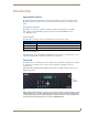
Introduction Control Keys Command Keys LCD Command Screen Take Key Arrow Keys Number Keys (0 through 9) FIG. 2 CP-10 LCD & control panel keys Note: The following keys are not currently implemented: Special, Undo, Comma, Period, and Up and Down Arrows. Keys & Functions Cancel Key – cancels an incomplete command and returns the panel to the Command screen. Cannot undo a completed operation, i.e.
Executing Switches Executing Switches A switch is an active connection between an input (source) device and one or more output (destination) devices. The signals routed in a switching operation are individual signals or groups of individual signals coming through the connectors on the rear of an enclosure. You can execute switches from the CP-10 using the steps below. Switching Level All switches are executed on a specific level (virtual matrix).
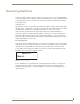
Executing Switches The example following switches Input 1 to Output 2 on Level 0. To execute a switch: 1. At the Command screen, press the Change Key. The Change screen appears. 2. At the Change screen, press the Level Key and enter “0.” 3. Press the Input Key and enter “1.” 4. Press the Output Key and enter “2.” 5. Press the Take Key. Input 1 is routed to Output 2, and the system returns to the Command screen. To execute a switch with multiple outputs: 4 1. Complete Steps 1 through 3 above.
Verifying Signal Status Verifying Signal Status Signal status can be verified to confirm that a switch has executed properly or to confirm correct routing to multiple outputs (destinations) without accidently executing or disconnecting switches. Input status and output status both function on the CP-10 Control Panel. An output can only receive a signal from one input (source); therefore verifying the status of an output will display only the one input it is currently receiving a signal from.
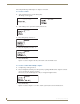
Verifying Signal Status No outputs – If no outputs are routed to the specific input, “DIS” (disconnect) displays in the Output field. The Status screen below indicates that Input 2 is not routed to any outputs. 5. Press the Status Key to return to the Status screen and select another signal to verify. Or Press the Cancel Key to return to the Command screen. The following example verifies the signal status of Output 9 on Level 0. To verify the status of an output signal: 6 1.
Executing Presets Executing Presets Global & Local Presets Overview Global and local presets are predefined sets of switches that can easily be executed. Local Presets A local preset is a predetermined set of switches on a particular level (virtual matrix) that are routed simultaneously. They are stored in each enclosure’s configuration file and can be executed at any time. Local presets are not programmed (defined) at the factory.
Executing Presets Executing Local Presets Note: Executing a local preset does not change any system routings that are not part of the preset. Make sure the CP-10 is on the level (virtual matrix) where the local preset resides. To return to the Command screen at any time, press the Cancel Key. The example below executes Local Preset 6 on Level 0. To execute a local preset: 1. At the Command screen, press the Preset Key. The Global preset screen appears. 2.
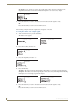
Executing Presets Defining Global Presets To return to the Command screen at any time, press the Cancel Key. The example below defines Global Preset 3, and the example on page 10 executes Global Preset 3. To define a global preset: 1. Route the system to the desired state. 2. At the Command screen, press the Preset Key. The Global Preset screen appears. 3. Press the Preset Key again. The program prompt appears with the cursor after the prompt.
Executing Presets Executing Global Presets To return to the Command screen at any time, press the Cancel Key. Note: When you execute a global preset, the system routes the switches immediately. To execute a global preset: 10 1. At the Command screen, press the Preset Key. The Global Preset screen appears with the cursor after the Execute prompt. 2. Enter “3.” 3. Press the Take Key. Global Preset 3 is executed and the system returns to the Command screen.
Checking the Software Version Checking the Software Version Use the following steps to check the software version of the CP-10 Control Panel. To check the software version: 1. Press the Cancel Key. 2. At the Command screen press the Program Key. The Software Version screen appears.
Installing a CP-10 Remote Control Panel Installing a CP-10 Remote Control Panel This chapter covers rack installation for the CP-10 Remote Panel (FG1090-216), as well as instructions for linking the panel to an enclosure. When the installation is complete, execute a test switch to make sure the system is working properly (see page 15).
Installing a CP-10 Remote Control Panel Connecting to AMX AutoPatch Matrix Switcher Communication Cable Requirements Two-conductor, 20 AWG, 7/28 strand cable with a drain wire or shield, such as Alpha 2412C (customer supplied) Maximum length of cable: 1,000 ft. (305 m) total, including linked panels AMX AutoPatch pigtail (provided) To connect a CP-10 Remote to an AMX AutoPatch Matrix Switcher: 1. Attach the two wires of the AMX AutoPatch pigtail to the communication cable. 2.
Installing a CP-10 Remote Control Panel Applying Power Power Requirements AMX AutoPatch wall transformer Or +7 VDC to +12 VDC @ 500 mA Important: Always use a UL approved power source. Be sure to check the power source documentation for information specific to that power source. The instructions below are for using the (optional) AMX AutoPatch wall transformer. If you use the AMX AutoPatch transformer, the side of the wire with the white stripe is positive and the other side is ground.
Installing a CP-10 Remote Control Panel Rack Installation CP-10 Remote Panels are designed to fit in a standard EIA 19 in. (48.26 cm) rack. Once the CP-10 Remote is wired, follow the rack installation instructions below. Tip: When placing control panels, keep in mind that the optimal viewing angle is at eye level. To install the CP-10 Remote in a rack: 1. Insert the wired panel through the rear of the rack. 2. Attach with front-mounting screws to hold it firmly in place (FIG. 8). FIG.
Installing a CP-10 Remote Control Panel 2. Press the Level Key and enter “0.” 3. Press the Input Key and enter “1.” 4. Press the Output Key and enter “2.” 5. Press the Take Key. Input 1 is routed to Output 2, and the system returns to the Command screen. If the system is not working properly, check all system connections and retry the test switch before contacting technical support (see page 18).
Appendix A – System Error Codes Appendix A – System Error Codes This appendix contains an overview of common error codes that can appear on a CP-10 Control Panel, provides basic troubleshooting strategies, and gives technical support contact information. Common System Error Codes The table below lists the error code, the name of the code, the meaning of the code, and some basic troubleshooting strategies (additional troubleshooting strategies are included on page 18).
Appendix A – System Error Codes Troubleshooting Error codes can appear either on the control panel or in a terminal emulation program, such as HyperTerminal. When you are using a control panel, one of the most common troubleshooting strategies is to resend the command to see if the error was simply a timeout error. When you are using BCS (Basic Control Structure) commands, one common troubleshooting strategy is to enter the command again. Often the command has simply been entered incorrectly (e.g.
1/09 2009 AMX©. All rights reserved. AMX and the AMX logo are registered trademarks of AMX. AMX reserves the right to alter specifications without notice at any time. It’s Your World - Take Control™ 3000 RESEARCH DRIVE, RICHARDSON, TX 75082 USA • 800.222.0193 • 469.624.8000 • 469-624-7153 fax • 800.932.6993 technical support • www.amx.