Instruction Manual Optima SD Distribution Matrix AutoPatch Matrix Switchers Release: 4/21/2009 Firmware v1.4.
AMX Limited Warranty and Disclaimer All products returned to AMX require a Return Material Authorization (RMA) number. The RMA number is obtained from the AMX RMA Department. The RMA number must be clearly marked on the outside of each box. The RMA is valid for a 30-day period. After the 30-day period the RMA will be cancelled. Any shipments received not consistent with the RMA, or after the RMA is cancelled, will be refused. AMX is not responsible for products returned without a valid RMA number.
Software License and Warranty Agreement • LICENSE GRANT. AMX grants to Licensee the non-exclusive right to use the AMX Software in the manner described in this License. The AMX Software is licensed, not sold. This license does not grant Licensee the right to create derivative works of the AMX Software. The AMX Software consists of generally available programming and development software, product documentation, sample applications, tools and utilities, and miscellaneous technical information.
Contents Contents ESD Warning .......................................................................................................1 Important Safety Information & Instructions .......................................................2 Information et directives de sécurité importantes...............................................3 Notices ................................................................................................................4 Overview & General Specifications .....................
Contents APWeb Expansion Board.................................................................................. 45 Overview ............................................................................................................................... 45 The APWeb Board ................................................................................................................. 46 System Setup..............................................................................................................
ESD Warning ESD Warning To avoid ESD (Electrostatic Discharge) damage to sensitive components, make sure you are properly grounded before touching any internal materials. When working with any equipment manufactured with electronic devices, proper ESD grounding procedures must be followed to ensure people, products, and tools are as free of static charges as possible. Grounding straps, conductive smocks, and conductive work mats are specifically designed for this purpose.
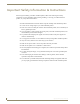
Important Safety Information & Instructions Important Safety Information & Instructions When using and installing your AMX AutoPatch product, adhere to the following basic safety precautions. For more information about operating, installing, or servicing your AMX AutoPatch product, see your product documentation. Read and understand all instructions before using and installing AMX AutoPatch products. Use the correct voltage range for your AMX AutoPatch product.
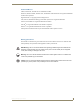
Information et directives de sécurité importantes Information et directives de sécurité importantes Veuillez vous conformer aux directives de sécurité ci-dessous lorsque vous installez et utilisez votre appareil AMX AutoPatch. Pour de plus amples renseignements au sujet de l’installation, du fonctionnement ou de la réparation de votre appareil AMX AutoPatch, veuillez consulter la documentation accompagnant l’appareil.
Notices Notices Copyright Notice AMX© 2009 (Rev A), all rights reserved. No part of this publication may be reproduced, stored in a retrieval system, or transmitted, in any form or by any means, electronic, mechanical, photocopying, recording, or otherwise, without the prior written permission of AMX.
Notices Trademark Notices AMX®, AutoPatch®, and NetLinx® are trademarks of AMX. Windows®, Windows 2000®, Windows NT®, and Windows XP Professional® are registered trademarks of Microsoft Corporation. HyperTerminal® is a copyright product of Hilgraeve Inc. 3M®, Desco®, Richmond Technology®, and Plastic Systems® are registered trademarks. Neuron® and LonTalk® are registered trademarks of Echelon. TosLink® is a registered trademark of the Toshiba Corporation.
Notices 6 Optima SD Instruction Manual
Overview & General Specifications Overview & General Specifications Applicability Notice The information in this manual applies to Optima SD (Slam Dunk) pre-engineered systems. For other types of Optima systems, see the Optima Instruction Manual.
Overview & General Specifications Optima SD Control Features Optima SD systems support three protocols: BCS* (Basic Control Structure), XNNet, and TCP/IP. Several control options are available. Multiple control methods can be used on the same system.
Overview & General Specifications Rear View The enclosures’s appearance, as viewed from the rear (FIG. 2), will vary depending on the configuration. Serial number Expansion slots CPU/Control board Input connectors I/O boards Output connectors Power receptacle FIG.
Overview & General Specifications The following sections briefly introduce the hardware on the rear of an enclosure. CPU/Control Board The CPU is to the left of the input connectors on the rear of the enclosure (FIG. 3). Expansion slots System Status indicator – Blinks either green or red to indicate system status Communication Status indicator REMOTE port – XNNet communication link port for linking to AMX AutoPatch control devices (e.g.
Overview & General Specifications Input/Output Boards Board slots 1 and 2 Board slots 3 and 4 Board slots 5 and 6 FIG. 4 Input/Output boards in an Optima SD enclosure An Optima SD (3 RU) enclosure has six board slots. The double boards each fill two board slots and have two rows of connectors.
Overview & General Specifications Optima SD Specifications General Specifications Parameter Value Approvals CE, UL, cUL Humidity 0 to 90% non-condensing Operational Temperature 32° F to 110° F (0° C to 43° C) MTBF 92,000 hr. AC Power* 100 to 240 VAC, single phase (50 Hz to 60 Hz) 3.3 A @ 115 VAC max. 1.6 A @ 230 VAC max. Power Consumption (max.) 260 Watts per enclosure Power Consumption (typical) 135 Watts per fully loaded enclosure Thermal Dissipation (max.) 887 BTU/hr.
Overview & General Specifications Control Options Optima SD systems support three different protocols: BCS (as ASCII characters sent through the CONTROL / RS-232 port), XNNet, and TCP/IP. Several different control options are available for Optima SD systems, and multiple control methods can be used on the same system.
Overview & General Specifications 14 Optima SD Instruction Manual
Installation & Setup Installation & Setup Site Recommendations When placing the enclosures, follow the recommendations and precautions in this section to reduce potential installation and operation hazards. Environment Choose a clean, dust free, (preferably) air-conditioned location. Avoid areas with direct sunlight, heat sources, or high levels of EMI (Electromagnetic Interference). To make control panel operations easier, mount the enclosure with the control panel in the rack at eye level.
Installation & Setup Mechanical (Rack) Loading When installing equipment in a rack, distribute the weight to avoid uneven mechanical loading. Circuit Overloading When connecting the equipment to the supply circuits, be aware of the effect that overloading the circuits might have on over-current protection and supply wiring. Reliable Earthing (Grounding) Reliable earthing of rack-mounted equipment should be maintained. If not using a direct connection to the branch circuit (e.g.
Installation & Setup Rack Installation & System Setup The Optima SD enclosures can be mounted in a standard EIA 19 in. (48.26 cm) rack. Rack installation ears are included, and directions for mounting the rack ears are included in the rack installation instructions (see page 19). Important: The system requires at least one empty rack unit above and below each enclosure to allow adequate airflow; three empty rack units are recommended.
Installation & Setup Installation Procedure A flow chart showing the installation sequence is in FIG. 5. The procedure following provides general steps with references to detailed information found in later sections of the manual. FIG. 5 Installation procedure Caution: To prevent overheating and airflow restriction, avoid placing high heat producing equipment directly above or below the enclosures.
Installation & Setup Rack Installation Caution: To prevent overheating and airflow restriction, avoid placing high heat producing equipment directly above or below the enclosures. The system requires a minimum of one empty rack unit above and below (three empty rack units are recommended). Verify that the openings on the sides of the enclosures are not blocked and do not have restricted air flow.
Installation & Setup Important: Enclosures must be cabled correctly after linking. To ensure that the correct signal cables are attached to the correct enclosure, check the “AutoPatch Connector Guide” that shipped with the system, as well as the system / enclosure numbers on the rear of each enclosure. Link Cable AMX provides an RJ-45 crossover link cable for direct linking between Optima SD enclosures. The cable is wired to TIA/EIA-568-A on one end and TIA/EIA-568-B on the other end.
Installation & Setup Linking an Optima SD System Optima SD enclosures are directly linked to each other via their ENC LINK ports (FIG. 8). The total distance between the two linked enclosures cannot exceed 100 ft. (30.5 m). Cable Length Requirements Network Segment Between two Optima SD enclosures Cable Type Maximum Distance RJ-45 crossover 100 ft. (30.5 m) To link an Optima SD system: 1. Insert one end of the crossover cable into the first enclosure’s ENC LINK (RJ-45) port. 2.
Installation & Setup Attaching External Controllers The Optima SD can be controlled by attaching an external control device that uses one of the communication protocols listed below: BCS (Serial) – ASCII sent over a null modem serial cable via the CONTROL (RS-232) port XNNet – AMX AutoPatch protocol via the REMOTE port or CONTROL (RS-232) port; AMX AutoPatch control and accessory devices usually connect via the REMOTE port Important: The ENC LINK (Ethernet RJ-45) port on the CPU is not for a TCP/IP connect
Installation & Setup Attaching Serial Controllers An external serial controller is any device that can send and receive ASCII code over an RS-232 (null modem) serial cable attached to the CONTROL (RS-232) port on the enclosure’s CPU. PCs are common serial controllers. Once a PC is attached to an Optima SD enclosure, the system can be controlled by running APControl software on the attached PC (see the AMX AutoPatch CD).
Installation & Setup 2. Plug one end of the null modem serial cable into the CONTROL (RS-232) port on the enclosure (FIG. 10). Null modem serial cable FIG. 10 Attach null modem serial cable to CONTROL port 3. 4. Plug the other end of the serial cable into the serial port on the serial controller/device. Open the serial communication software and set the port settings to match the Optima SD default settings (see table to the right).
Installation & Setup Attaching Remote XNNet Control Devices A remote XNNet control device is any device that sends and receives XNNet protocol over the REMOTE port. AMX AutoPatch XNNet control devices include SBC control pads, Preset SBC control pads, and remote control panels. The instructions below are for attaching a device to the REMOTE port, which is located on the CPU board. For specific product information, see the individual device’s documentation.
Installation & Setup Attaching Inputs & Outputs Input and output connectors are the attachment points for source and destination devices that connect to the system. Looking at the rear of each enclosure, the inputs (for sources) are on the left side of each board, and the outputs (for destinations) are on the right side of the board. The number and type of connectors depend on the number and type of input/output boards. Input and output connectors are numbered separately.
Installation & Setup Signal Types & Connectors The signal types and connectors for an Optima SD system are: 500 MHz video over BNC connectors Hi-Z sync over BNC connectors Stereo audio (balanced or unbalanced) over pluggable 5-position terminal block connectors For signal specifications for these signals, see the chapters for the individual board types: 500 MHz on page 35, Hi-Z sync on page 37, and stereo audio on page 39.
Installation & Setup Wiring Stereo Audio Connectors (5-position terminal block) The stereo audio connectors for the Optima SD are pluggable 5-position terminal block. For stereo audio signal specifications, see the “Stereo Audio Input/Output Boards” chapter (see page 39). Wiring Sources & Destinations Source and destination devices will require either balanced (differential) or unbalanced (single-ended) connections. FIG.
Installation & Setup Applying Power & Startup The universal power receptacles on the enclosures will accept all major international standard power sources. (Standard US power cords are provided for installations within the US.) Maximum power specifications are on the power receptacle (also listed on page 12). Always use an earth-grounded power cord / system with an Optima SD system. The source electrical outlet should be installed near the Optima SD enclosures, easily accessible, and properly grounded.
Installation & Setup Serial Control Device Startup If you have not already done so, attach the serial control device to an enclosure (see page 22) and open the control program. AMX Control Devices The Optima SD is compatible with a number of AMX control devices. For control programming information, see the instruction manual for the specific device. APControl 3.0 If you are using APControl 3.0, install and open the program. Follow the directions in the setup wizard.
Installation & Setup Executing a Test Switch We recommend executing a test switch to verify the system is working properly before attaching all inputs and outputs. Aside from having signal cables attached, the system is ready to execute switches when it ships from the factory. Important: The Optima SD ships from the factory with a default switch of Input 1 to all output. Before executing the test switch, you will need to disconnect the factory default switch.
Installation & Setup To disconnect the factory default switch using the control panel: 1. Press the Function Key. The Function menu appears. 2. Locate Disconnect by scrolling with the Control Dial. 3. Press the Select Key. The system is in Disconnect Mode (all the available Input and Output Keys turn blue). Current virtual matrix – VM 0 4. Press Input Key 1. Input Key 1 turns white, indicating that it is selected. 5. Press the Take Key.
Installation & Setup 5. Press the Take Key. Input 2 switches to Output 1, and the keys turn blue. The panel remains in Change Mode until the Function Key is pressed. AMX Control Device For executing and disconnecting switches using an AMX control device, see the specific control device documentation. APControl 3.0 or APWeb Directions for executing and disconnecting switches using APControl 3.0 are found in its Help file.
Installation & Setup Troubleshooting If the test switch did not execute correctly: Check the power indicator on the front of the enclosures. If it is not illuminated, check the power cords. Verify the status of the test switch. If using BCS commands, enter: SL0O2T. If “SL0O2T(1)” appears, the test switch is routed. If the status returns as routed correctly, the system established a connection between the specified input and output connectors within both enclosures.
500 MHz Video Input/Output Boards 500 MHz Video Input/Output Boards Applicability Notice This chapter pertains to 500 MHz video input/output boards (with BNC connectors) contained in the Optima SD systems in the following table: Signal(s) Configuration System Sales # RGBHV 16x16 FGP46-1616-560 RGBHV+Stereo 16x16 FGP46-1616-567 RGBHV 8x16 FGP46-0816-560 RGBHV+Stereo 8x16 FGP46-0816-567 RGBHV 12x12 FGP46-1212-560 RGBHV+Stereo 12x12 FGP46-1212-567 RGBHV 16x8 FGP46-1608-560 RGBHV+Stereo
500 MHz Video Input/Output Boards 500 MHz Video Input/Output Boards Specifications Applies to 500 MHz video I/O boards in the Optima SD systems listed on the previous page. Specifications Parameter Conditions Value Frequency Response 1 to All +4/-3.0 dB to 500 MHz or better Crosstalk f = 5 MHz f = 30 MHz f = 150 MHz <-70 dB <-60 dB <-33 dB Signal to Noise Ratio (SNR) Vin = 0.7 V, 100 IRE >65 dB Return Loss f = 5 MHz <-45 dB Input Level (max.) ±1.
Hi-Z Sync Input/Output Boards Hi-Z Sync Input/Output Boards Applicability Notice This chapter pertains to Hi-Z sync input/output boards (with BNC connectors) contained in the Optima SD systems in the following table: Configuration System Sales # RGBHV Signal(s) 16x16 FGP46-1616-560 RGBHV+Stereo 16x16 FGP46-1616-567 RGBHV 8x16 FGP46-0816-560 RGBHV+Stereo 8x16 FGP46-0816-567 RGBHV 12x12 FGP46-1212-560 RGBHV+Stereo 12x12 FGP46-1212-567 RGBHV 16x8 FGP46-1608-560 RGBHV+Stereo 16x8 FGP4
Hi-Z Sync Input/Output Boards Attaching Cables When attaching video input and output cables, refer to the sheet labeled “AutoPatch Optima Connector Guide” that shipped with the system. The sheet shows where to attach each cable on the rear of each enclosure. Follow the sheet exactly; the system was programmed at the factory to operate only as indicated on the sheet. For multi-enclosure systems, each enclosure will be numbered (e.g.
Stereo Audio Input/Output Boards Stereo Audio Input/Output Boards Applicability Notice This chapter pertains to stereo audio input/output boards with digital gain control contained in the Optima SD systems in the following table: Signals Configuration System Sales # RGBHV+Stereo 16x16 FGP46-1616-567 RGBHV+Stereo 8x16 FGP46-0816-567 RGBHV+Stereo 12x12 FGP46-1212-567 RGBHV+Stereo 16x8 FGP46-1608-567 FIG.
Stereo Audio Input/Output Boards Stereo Audio Input/Output Boards Specifications Applies to stereo audio boards contained in the Optima SD systems listed on the previous page. Specifications Parameter Conditions Value Frequency Response 20 Hz to 20 kHz THD + Noise f = 20 Hz to 20 kHz, Vin = -10 to +10 dBu <0.03% f = 20 Hz to 20 kHz, Vin = 0 to +22 dBu <±0.2 dB <0.
Stereo Audio Input/Output Boards To attach stereo audio input and output wires: 1. Unscrew the clamps on the audio connector. 2. Insert the wires (FIG. 24) for wire placement for balanced and unbalanced audio) and firmly re-tighten the clamps to make proper connections. Unbalanced audio Balanced audio FIG.
Stereo Audio Input/Output Boards Adjusting Output Volume Volume (Digital Gain) Output volume can be adjusted using either a control panel with volume adjustment (see the CP-15 Control Panel Instruction Manual) or BCS (Basic Control Structure) commands from an external controller. BCS Volume Adjustment Volume can be adjusted using one of three BCS command methods: Absolute, Relative, or Increment/ Decrement.
Stereo Audio Input/Output Boards To adjust digital input gain using the BCS Absolute Method: 1. Enter the command below. Replace the “#”s with the level and input number(s) and replace “^^^” with the decibel level. Enter the decibel level as a decimal number to the tenth place without the decimal point (e.g., -5 dB is entered as -50).
Stereo Audio Input/Output Boards 44 Optima SD Instruction Manual
APWeb Expansion Board APWeb Expansion Board Applicability Notice This chapter pertains to the Optima 3 RU APWeb expansion board, FG1046-313, which works in Optima SD systems. APWeb expansion board FIG. 26 APWeb expansion board Overview An APWeb board can be ordered pre-installed in an Optima SD enclosure or as an upgrade for an existing Optima SD enclosure. The APWeb board is located in one of the two expansion slots to the left of the CPU (FIG. 26).
APWeb Expansion Board The APWeb Board The APWeb board has a TCP/IP Ethernet link connector, three indicator LEDs, and a Service switch. Ethernet Speed Indicator Ethernet Link Indicator Power Indicator TCP/IP Ethernet Link Connector Service Switch (set for normal function) FIG. 27 The APWeb board TCP/IP Ethernet Link Connector The APWeb board has a TCP/IP Ethernet (RJ-45) link connector that handles Ethernet 10/100 connections for 10 Mbps (megabits per second) and 100 Mbps.
APWeb Expansion Board System Setup The system setup example in FIG. 28 illustrates an Optima SD enclosure with an APWeb expansion board connected to a LAN. Both computers in the illustration have access to the Optima SD. If only one computer will be used, the APWeb board can be connected directly to the computer’s network card. Optima SD enclosure with APWeb board FIG.
APWeb Expansion Board Adding an APWeb Board If the APWeb board has been pre-installed, go directly to the instructions on page 49 for cabling and applying power to the enclosure. If the APWeb board was ordered to upgrade a system, complete the steps below and then see the instructions on page 49 for cabling and applying power. ESD Warning: To avoid ESD (Electrostatic Discharge) damage to sensitive components, make sure you are properly grounded before touching any internal Optima SD materials.
APWeb Expansion Board Cabling & Applying Power After installing the APWeb board, connect it to a LAN or a Network Interface Card (NIC) in a PC. During the initial setup (see below), the APWeb board discovers the system. After the initial setup, it does not need to rediscover the system (even if power is cycled). If connecting to a PC, the PC’s settings may need to be changed (contact your Network Administrator). Cable Requirements LAN Connection – Use an RJ-45 straight-through patch cable.
APWeb Expansion Board Testing the Connection The connection between the APWeb board and the LAN should be tested to complete the setup. The instructions below open the APWeb site to the user’s Home page, which has limited access to the APWeb server. If you need full access to configuration and security settings, see the APWeb Instruction Manual on the AMX AutoPatch CD or at www.amx.com. To test the connection: 1. Launch a browser on your computer. 2. Type http://192.168.0.
APWeb Expansion Board If APWeb opens but appears to be stalled (the message “Waiting to detect AutoPatch system on the network” displays for more than 30 seconds): Connect the PC directly to a serial port* on one of the enclosures with a null modem cable. Open HyperTerminal (or other terminal emulation program). Power cycle the Optima SD; the splash screen appears with the firmware version number. Verify that the firmware version is 1.2.0 or greater (see the graphic below).
APWeb Expansion Board Enter the diagnostic command ~scrv3i3! Verify that one of the [type] lines displays the following configuration: BCS mode RS232 port, 9600 (8/1/N/E/NS) or BCS mode RS232 port, 9600 (8/1/N/NE/NS) ~scrv3i3! [3:Communication Interfaces] count = 3 [interface 1] detected [type] BCS mode RS232 port, 9600 (8/1/N/E/NS) [interface 2] detected [type] MCF5272 FEC Ethernet Controller [interface 3] detected [type] Neuron bridge v1.0.
Appendix A – Managing Configuration Files Appendix A – Managing Configuration Files Applicability Notice This appendix applies to XNConnect version 2.8.0. XNConnect’s version information is found under its Help menu. Version 2.8.0 supports full Device Discovery through AMX’s AutoPatch Duet module (firmware v1.4.0 or higher is required).
Appendix A – Managing Configuration Files AMX AutoPatch CD Information If you cannot locate the AMX AutoPatch CD that shipped with your system and your AMX account has the required permissions, you can download the newest version of XNConnect from www.amx.com. An INI file Updater for updating XNConnect is available on the AMX website under Tech Center \ AutoPatch Tools; an account is not required. If you need an .
Appendix A – Managing Configuration Files 4. Select XNConnect. The XNConnect program opens. Getting Started dialog box When XNConnect is open, use either of the following options for accessing the configuration: Discover the system; see below. Open the copy of the .xcl configuration file located on the AMX AutoPatch CD; see page 56.
Appendix A – Managing Configuration Files Opening a Configuration File The process of modifying a configuration file starts by opening it with XNConnect. After the modifications are complete, the new configuration information must be loaded onto the system to implement the changes. Important: Even if XNConnect is already on your PC, install the newest version that shipped on the same CD as the configuration file.
Appendix A – Managing Configuration Files Navigating the Interface XNConnect displays configuration information in two panes. The graphics are located in the left pane, and the properties of the currently selected graphic are in the right pane. At the top of the left pane are two tabs, Hardware and Virtual Matrices, for accessing the Hardware and Virtual Matrix views (see below).
Appendix A – Managing Configuration Files Multiple Signal Paths In Optima SD systems, each matrix is a signal path. When you select a connector in the virtual matrix view, the properties box in the right pane indicates the signal and the signal path for the connector. If the signal has multiple signal paths (e.g., stereo audio signals), each of the signals will be displayed and each signal path will display an appended number. In the example shown (FIG.
Appendix A – Managing Configuration Files 4. Enter the new name in the Input Text dialog box and click OK. The new channel name appears in the Name field. Name Field (displays selected channel) Customized Channel Name Selected Channel Enter Channel Name Default Channel Name Note: If a channel is in more than one VM (virtual matrix), you must repeat Step 4 for the channel in each of the VMs. 5. Customize additional channels by repeating Steps 3 and 4. 6. Load the .
Appendix A – Managing Configuration Files 3. Enter a single digit between one and eight (inclusive) in each field. 4. Check the box for Configure Password Immediately. Important: If you use the Configure menu instead of checking the box, the only option that will load password information is Configure \ Configure Special - Hardware \ Configure All Passwords. 5. Click OK.
Appendix A – Managing Configuration Files 4. Enter a name for the new preset (descriptions are optional and do not display outside of XNConnect). 5. Click OK. The Modify Preset dialog box opens. 6. For the first switch, click the source channel (input) and one or more destination channels (outputs). Select multiple destination channels by holding down the Control key while selecting the channels.
Appendix A – Managing Configuration Files Loading an .xcl Configuration File Once modifications have been made to the configuration file, the new file must be loaded onto the system’s CPU for the changes to be implemented. Important: When loading any part of a configuration file, the matrix switcher must not be actively switching. We recommend disconnecting any external controllers to ensure that no switches are executed during the loading of the file.
Appendix B – Programmer’s Interface for System Diagnostics Appendix B – Programmer’s Interface for System Diagnostics System Component Information The Optima SD displays system information in its splash screen* for diagnostic purposes. The information indicates the current status and well-being of the system components.
Appendix B – Programmer’s Interface for System Diagnostics Verbosity Settings The verbosity (v) settings (v0, v1, v2, v3) correspond to the level of detail that will be displayed, with v0 being the lowest level of detail and v3 being the highest level. Component Settings Detailed information for a single system component can be specified by using its identity (i) number setting (i0 through i5) in the following table.
Appendix B – Programmer’s Interface for System Diagnostics Splash Screen Examples Following are four examples of splash screen information that could be displayed when different verbosity/component settings are specified. Depending on the amount of detail provided, you may need to scroll to see the entire display. Use the first example to check the host software (IOS) version and the hardware driver (appcode) version. ~scrv1i1! [1:Enclosure] AutoPatch Optima [host software] v3.0.2 [hardware driver] v1.4.
Appendix B – Programmer’s Interface for System Diagnostics Splash Screen Examples (continued) ~scrv3i4! [4:Hardware Boards] detected [io boards] count = 5 [board 1] 40d5 [board 2] 40d5 [board 3] 40d5 [board 4] 40fc [board 5] 4180 FIG. 37 Display for v3i4 (verbosity 3, component 4) ~scrv3i5! [5:VM Configuration] count = 3 [VM 0] ‘RGBHVA2’ 12x4x5 [VM 1] ‘RGBHV’ 12x4x4 [VM 2] ‘A2’ 12x4x1 [VM 0 master] 0x0 0 0 1 (self) [VM 1 master] 0x0 0 0 1 (self) [VM 2 master] 0x0 0 0 1 (self) FIG.
Appendix C – Replacing I/O Boards Appendix C – Replacing I/O Boards This appendix covers the procedure to replace or add an Input/Output (I/O) board in an Optima SD enclosure. The number of input and output signals an enclosure can switch is determined by the number and type of connectors on each board and by the number of boards. An Optima SD 3 RU enclosure holds two or three double boards.
Appendix C – Replacing I/O Boards Removing I/O Boards To remove an I/O board: 1 1a: Remove the five screws indicated (four on top and one on the side). 1b: Remove the rack ear indicated (four screws). Stand the enclosure on this side for Steps 2 and 3. Screw will be in one of these 2 holes 1a 1b 1a FIG. 39 Remove 5 screws & rack ear (4 screws) 2 2a: Remove the three screws indicated. 2b: Remove expansion plate (two screws). 2b Expansion plate 2a Screw will be in one of these 2 holes FIG.
Appendix C – Replacing I/O Boards 3 3a: Carefully pull the CPU/board unit straight out of the enclosure frame. 3b: Pull up on the CPU board, wiggling slightly to loosen it from the board unit. Tip the board unit to the left for Step 4. Avoid pins when pulling out and when pulling up 3b CPU Board unit 3a FIG. 41 Pull CPU/board unit straight out & remove CPU 4 4a: Remove the side screw. 4b: Remove the side slide-key. Stand the board unit on the slide-key end for Steps 5 and 6.
Appendix C – Replacing I/O Boards 5 Remove the two center slide-keys. Position with gold card edges at top Spacers Spacers not connected to boards fall free when slide-keys are removed Center slide-keys FIG. 43 Remove center slide-keys (2) 6 6a: Remove the two screws indicated. 6b: Remove the board and place in an ESD approved static shield bag and set aside. 6b 6a Double-connector board requires removal of 2 screws FIG.
Appendix C – Replacing I/O Boards Replacing I/O Boards To install a replacement I/O board: 1 1a. Insert the new board. 1b. Replace the two screws indicated. Tip the board unit to the left. Raised circles 1a 1b Small holes next to screw holes will fit over small raised circles on board FIG. 45 Insert new board(s) & replace 2 screws 2 2a. Replace the side slide-key. 2b. Replace the side screw. 2c.
Appendix C – Replacing I/O Boards 3 3a. Insert the left slide-key (tab up) through the spacers, adding spacers as needed. 3b. Insert the right slide-key (tab down) under the left key and through the spacers. Dual-connector boards require two spacers 3a Tab down 3b Tab up FIG. 47 Insert left & right slide-keys through spacers Note: The number and placement of spacers varies per enclosure size and configuration. Dual-connector boards require two spacers.
Appendix C – Replacing I/O Boards 5 5a. Replace the three screws indicated. 5b. Replace the expansion plate (requires two screws). 5b Expansion plate 5a Screw will fit into one of these 2 holes FIG. 49 Replace 3 screws & expansion plate (2 screws) 6 6a. Replace the five screws indicated (four on top and one on the side). 6b. Replace the rack ear (requires four screws). Screw will fit into one of these 2 holes 6a 6b FIG.
Appendix C – Replacing I/O Boards Updating the System Configuration The configuration file stored in the CPU may or may not need to be updated, depending on the type of board being installed. When an I/O board is replaced with the same type of board, the configuration file will not need to be updated. When an I/O board is added to a previously empty slot (an upgrade) in a system, or if the replacement is a different type of board, the system’s configuration file must be updated before the board will work.
Appendix C – Replacing I/O Boards 10. For XNConnect version 2.4.0 and greater – from the Configure menu, select Configure All. The system automatically reboots all devices. Or For XNConnect versions prior to 2.4.0 – from the Configure menu, select Reboot All Devices. 11. Execute a test switch (see page 31) that includes a signal routed on the new board to ensure the system is working correctly. If the test switch does not execute correctly, contact technical support (see page 34).
Appendix C – Replacing I/O Boards 76 Optima SD Instruction Manual
4/09 ©2009 AMX. All rights reserved. AMX and the AMX logo are registered trademarks of AMX. AMX reserves the right to alter specifications without notice at any time. It’s Your World - Take Control™ 3000 RESEARCH DRIVE, RICHARDSON, TX 75082 USA • 800.222.0193 • 469.624.8000 • 469-624-7153 fax • 800.932.6993 technical support • www.amx.