
Instruction manual


Overview & General Specifications
9
Optima SD Instruction Manual
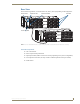
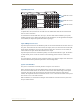
Rear View
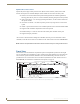
The enclosures’s appearance, as viewed from the rear (FIG. 2), will vary depending on the configuration.
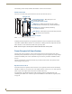
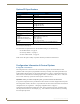
Rear View Components
CPU/Control board
Power receptacle and specifications
Input/output boards (number of connectors will vary depending on the system’s configuration)
Two expansion/control slots (one may contain an APWeb expansion board if pre-ordered)
Serial number
FIG. 2 Rear view 16x16 RGBHV+Stereo Optima SD system (RGB enclosure linked to HV with stereo enclosure)
Input connectors
Output connectors
I/O boardsExpansion slots CPU/Control boardSerial number
Power receptacle