
Instruction manual


500 MHz Video Input/Output Boards
36
Optima SD Instruction Manual
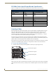
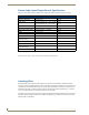
500 MHz Video Input/Output Boards Specifications
Applies to 500 MHz video I/O boards in the Optima SD systems listed on the previous page.
AMX reserves the right to modify its products and their specifications without notice.
Attaching Cables
When attaching video input and output cables, refer to the sheet labeled “AutoPatch Optima Connector
Guide” that shipped with the system. The sheet shows where to attach each cable on the rear of each
enclosure. Follow the sheet exactly; the system was programmed at the factory to operate only as
indicated on the sheet. For multi-enclosure systems, each enclosure will be numbered (e.g., “Chassis 1
of 2”) on a label located on the left side (near the power receptacle).
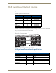
The input connectors (white BNCs) are on the left side of each 500 MHz video board, and the output
connectors (black BNCs) are on the right side. Input and output connectors are numbered separately. The
number of BNC connectors depends on the 500 MHz video I/O configuration.
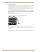
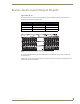
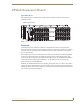
The example in FIG. 20 shows a BNC cable attached to Output 7 on each board to route the R, G, and B
components of an RGBHV signal. (The H and V components are routed on the second enclosure.)
To connect video inputs and outputs:
1.
Fasten the cables onto the input and output BNC connectors per signal type (FIG. 20).
Make sure the video cable is connected to the correct BNC connector on the correct enclosure. 500 MHz
video boards look similar to Hi-Z sync boards, but the “AutoPatch Optima Connector Guide” identifies
them.
Specifications
Parameter Conditions Value
Frequency Response 1 to All +4/-3.0 dB to 500 MHz or better
Crosstalk f = 5 MHz
f = 30 MHz
f = 150 MHz
<-70 dB
<-60 dB
<-33 dB
Signal to Noise Ratio (SNR) Vin = 0.7 V, 100 IRE >65 dB
Return Loss f = 5 MHz <-45 dB
Input Level (max.) ±1.5 V
Input Impedance 75 ohms
Output Level (max.) ±1.5 V
Output Impedance 75 ohms
Connector Type BNC
FIG. 20
Fasten cables onto input and output BNC connectors
Connectors for R signals
Connectors for G signals
Connectors for B signals