
Instruction manual

Appendix D – Adding or Replacing I/O Boards
147
Optima Instruction Manual
Appendix D – Adding or Replacing I/O Boards
This appendix covers the procedure to add or replace an Optima input/output (I/O) board. The procedure
for replacing boards is the same for 2 RU and 3 RU enclosures.
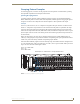
Input/output boards can be added to a partially filled enclosure to expand a system’s capabilities or
increase an enclosure’s possible signal routings. An Optima 2 RU holds up to four boards (or two
double-connector boards) while an Optima 3 RU holds up to six boards (or three double-connector
boards).
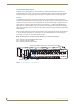
Expansion boards (e.g., APWeb, XNNet boards) can also be added to an enclosure. For installation
instructions for an expansion board, see the chapter for that specific board.
Important: Adding or replacing boards should only be done by personnel trained to handle ESD
sensitive parts and assemblies.
Items Required
Optima I/O board(s)
Phillips #1 screwdriver
ESD wristband and cord with alligator clip
Updated configuration file (see “Configuration Requirements” below to determine if required)
Configuration Requirements
If a board is replaced with the same type of board or if the system was configured for
expansion with the same type of board, the configuration file does not need to be updated.
If a board is added to a previously empty slot as part of an unplanned upgrade or if a board is
replacing a different type of board, the configuration must either be discovered (see page 124)
or requested from technical support (see page 40) and uploaded to the system for the new
board to work.
8x8 DVI Board: If installing or replacing this type of board, refer to the “EDID Programmer” appendix
(see page 157) for information on EDID Programmer software.
8x8 HDMI Board: If installing or replacing this type of board, refer to the “HDMI I/O Board” chapter
for additional setup information (see page 76).
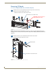
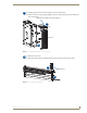
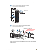
Before Starting
Unplug the power cord on the rear of the enclosure.
Multiple-enclosure system – label and disconnect link cables.
Label and disconnect all signal cables and if applicable, any cables for external control.
If the enclosure is in a rack, remove it and place on the work surface.
ESD Warning: To avoid ESD (Electrostatic Discharge) damage to sensitive components, make sure
you are properly grounded before touching any internal Optima materials. Use an ESD wristband
and cord with an alligator clip attached to a good ground source.